Notes to a video lecture on http://www.unizor.com
Direct Current - Ohm's Law - Problems 4
Problem A
Given a circuit presented on a picture below.
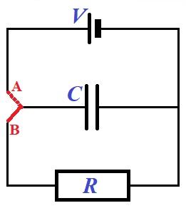
Initially, a red switch is in position A to fully charge a capacitor of capacity C from a battery producing a direct current with voltage V.
When a capacitor is fully charged, a switch is moved to position B, disconnecting a capacitor from a battery and forming a new circuit that includes only a fully charged capacitor and a resistor of resistance R.
When a switch is in position B, a
capacitor starts discharging its charge through a resistor. It's charge
will gradually diminish to zero, when all excess electrons on its one
plate will flow through a resistor to a plate with deficiency of
electrons.
During this process of discharge the electric current in a circuit that
contains a capacitor and a resistor will change from some maximum value
in the beginning of this process to zero, when the discharge is
completed.
Find the charge on a capacitor Q(t) and an electric current flowing trough a resistor I(t) as functions of time t.
Solution
Assume, our switch is in position A, and we are at the charging stage, when the battery of voltage V is charging a capacitor of capacity C.
The capacity of a capacitor is defined as the constant ratio of a charge
accumulated by a capacitor to a voltage applied to its plate (see
"Capacitors" lecture in the "Electromagnetism - Electric Field"
chapter):
C = Q/V
Therefore, the full charge of a capacitor at the end of the first stage of charging is V·C.
Then we flip a switch into position B, starting the second stage - discharging of a capacitor through a resistor.
At the beginning of this second stage a capacitor is fully charged. So, at time t=0 its charge is
Q(0) = V·C
The charge on a capacitor at any time produces a voltage between its plates
V(t) = Q(t)/C
This voltage produces a current flowing through a resistor I(t) that, according to the Ohm's Law, should be equal to
I(t) = V(t)/R
From the two equations above we conclude
Q(t)/C = I(t)·R
This is our first equation that connects two time-dependent (that is,
functions of time) variables - an electric current in a circuit I(t) and a charge on a capacitor Q(t).
The second functional equation is, basically, a definition of an
electric current as the rate of electric charge flowing in a circuit
(that is, amperage is how much electricity in coulombs flows through a circuit per unit of time - a second).
Mathematically speaking, an electric current is the first derivative of
an electric charge by time, taken with a sign that depends on the
direction of the change of the charge (plus if the charge is increasing and minus if decreasing):
I(t) = −dQ(t)/dt
Considering the charge Q(t) is decreasing and, therefore,
its derivative is negative, while we would like the electric current to a
be a positive number, we have to use a minus sign in this equation.
This is our second functional equation (that happens to be differential)
connecting two functions - an electric current in a circuit I(t) and a charge on a capacitor Q(t).
Now we have two functional equations, one of them is differential, and an initial condition:
Q(t)/C = I(t)·R
I(t) = −dQ(t)/dt
Q(0) = V·C
It's up to our mathematical skills to solve this system of equations.
First, we substitute I(t) from the second equation into the first, getting a differential equation for Q(t)
Q(t)/C = −R·dQ(t)/dt
This can be converted into
dQ(t)/Q(t) = −dt/(R·C)
or
d[ln(Q(t))] = d[−t/(R·C)]
If differentials of two functions are equal, the functions themselves
are just separated by a constant that can be determined using the
initial condition. Let denote that constant as K.
ln(Q(t)) = −t/(R·C) + K
or, applying an exponent to both sides of this equation,
Q(t) = eK·e−t/(R·C)
It's time to use the initial condition Q(0)=V·C to determine the multiplier eK.
For t=0 the right side of an expression for Q(t) equals to eK. Therefore, this multiplier equals to V·C.
Therefore, the final expression for a charge on a capacitor as a function of time Q(t) is
Q(t) = V·C·e−t/(R·C)
So, a charge on a capacitor is exponentially diminishing.
From the expression of Q(t) we can find the expression on an electric current going through a resistor, using the equation
I(t) = −dQ(t)/dt
from which follows
I(t) = −d[V·C·e−t/(R·C)]/dt =
= −V·C·d[e−t/(R·C)]/dt =
= −(V·C)·(−1/(R·C))·e−t/(R·C) =
= (V/R)·e−t/(R·C)
Answer
Q(t) = (V·C)·e−t/(R·C)
The multiplier V·C is the initial full charge of a capacitor.
I(t) = (V/R)·e−t/(R·C)
The multiplier V/R is the current that would flow through a resistor, if there were no capacitor. This follows from the Ohm's Law.
