Thursday, December 27, 2018
Unizor - Physics4Teens - Mechanics - Problems on Power
Notes to a video lecture on http://www.unizor.com
Problems on Mechanical Power
Problem A
A car engine accelerates a car of mass m from the state at rest to speed V during the time T with constant acceleration along a straight line.
Ignore loss of mass due to burning fuel.
(a) What is the power of the car engine as a function of time?
(b) If engine's power is proportional to amount of fuel supplied to it
in a unit of time (fuel burring speed), how the fuel burning speed will
change over time to assure the kind of motion described in this problem?
Solution:
(a) a = V/T
F = m·a = m·V/T
S(t) = a·t²/2 = (V/T)·t²/2
W(t) = F·S(t) = (m·V/T)·(V/T)·t²/2 = m·V²·t²/(2T²)
P(t) = dW(t)/dt = (m·V²/T²)·t
(b) The fuel burning speed is linearly increasing with time. The faster a
car goes, as it accelerates, - the more power should be supplied to
assure the constant acceleration, and the faster fuel is burning.
Problem B
A car engine supplies constant power P to a car of mass m.
Find its speed and acceleration as a function of time.
Is speed linearly increasing with time?
Solution
We will use the general formula for power as a function of mass, speed and acceleration:
P(t) = m·V(t)·a(t)
or, since a(t)=dV(t)/dt,
P(t) = m·V(t)·dV(t)/dt
Therefore,
P(t)·dt = m·V(t)·dV(t)
In our case P(t) is constant P. Therefore,
P·dt = m·V(t)·dV(t)
Integrating this by time from t=0 to t,
P·t = m·V²(t)/2
From this we can find speed V(t):
V(t) = √2P·t/m
Acceleration is
a(t) = dV(t)/dt = √P·/(2m·t)
Speed is not linearly increasing with time, it is proportional to a
square root of time, which means that acceleration is monotonically
diminishes, while speed increases.
Problem C
A car engine supplies constant power P to a car of mass m.
How long would it take for a car to reach speed Vmax?
Solution
As we know,
P(t) = m·V(t)·a(t)
Since power P(t)=P - is constant, and acceleration is the first derivative of speed by time, this can be written as
P = m·V(t)·dV(t)/dt
Therefore,
P·dt = m·V(t)·dV(t)
Integrating this by time from t=0 to t,
P·t = m·V²(t)/2
From this we can find time t as a function of speed:
t = m·V²(t)/(2P)
Therefore, the time at the moment the speed is equal to Vmax equals to
tmax = m·V²max /(2P)
Obviously, the more powerful an engine is - the shorter will be the time interval it takes to achieve needed speed.
As an example, consider a car 2012 Tesla Model S 85 kWh .
It has a mass of 2108 kg and its engine develops the power of 310 Kw.
According to the formula above, the time it takes for this car to reach the speed of 60 miles/hour (26.8 m/sec) equal to
2108·26.8²/(2·310000) = 2.44(sec)
So, in theory, this car is capable to reach the speed of 60 miles/hour in just under 2.5 sec.
Wednesday, December 26, 2018
Unizor - Physics4Teens - Mechanics - Power
Notes to a video lecture on http://www.unizor.com
Definition of Mechanical Power
To analyze the motion, we often use a concept of speed.
Let's assume that an object moves in some inertial reference frame, and
the distance covered by it from its initial position along its
trajectory is a function of time S(t).
Recall the definition of speed of an object as the rate, at which this object covers the distance along its motion along a trajectory.
In case of a uniform motion we can simply divide the distance S, covered during time t, by the time t to get the speed:
V = S/t
In case of non-uniform motion the speed changes and at any particular moment of time t an instantaneous speed can be calculated using differentials:
V(t) = dS(t)/dt
To analyze the mechanical work performed to achieve certain results, we often use a concept of power.
Let's assume that something or someone performs certain work and, as the time goes by, the work performed is a function of time W(t).
The power is the rate, at which the work is performed.
If during the time t the work performed is W, we define the average power of the whoever or whatever performs the work as
P = W/t
Most likely, at equal in length but different time intervals the amount
of work performed will be different. For example, when a car starts, its
engine should give a car an acceleration, which requires more work per
unit of time than to maintain a constant speed on a smooth straight
road.
In cases like this we can talk about an instantaneous power as a function of time that can be calculated using differentials:
P(t) = dW(t)/dt
Consider an example of an object in uniform motion against the force of friction with a constant speed V.
The force F that moves it forward must be equal in
magnitude and opposite in direction to the force of friction to maintain
the constant speed. Since the friction is constant, the force F must be constant as well.
The distance S covered as a function of time t is
S(t) = V·t
Therefore, the work performed by the force F during the time t is
W(t) = F·S(t) = F·V·t
From the definition of power follows that the power this force F exhorts is
P(t) = dW(t)/dt = F·V
As an example, the car engine exhorts the same power and consumes the
same amount of gas per unit of time, if the car uniformly moves along a
straight road. This power is used to generate a force sufficient to
overcome the friction of wheels and air resistance.
Consider a more general case, when the motion is not uniform.
Assume, an object of mass m moves as a result of action of force F(t), where t is time. The distance it covers is S(t).
Then during an infinitesimal time interval from t to t+dt the work performed by this force will be
dW(t) = F(t)·dS(t)
Considering the Newton's second law,
F(t) = m·a(t),
where a(t) is acceleration.
Increment of distance is
dS(t) = V(t)·dt,
where V(t) is an object's speed.
Also, by definition of acceleration,
a(t) = dV(t)/dt
Therefore,
dW(t) = (m·dV(t)/dt)·V(t)·dt =
= m·V·dV(t)
Power exhausted by this force is, therefore
P(t) = dW(t)/dt =
= m·V·dV(t)/dt =
= m·V(t)·a(t)
From the definition of power as amount of work per unit of time or, more precisely, the first derivative of work by time
P(t) = dW(t)/dt
follows that the unit of measurement of power is joule/sec called watt.
Expanding the definition of joule as newton·meter,
1 watt = 1J/sec = 1N·m/sec
Obvious extensions of unit of power watt are
kilowatt = 1,000 watt and
megawatt = 1,000,000 watt.
There is an old unit of power called horsepower.
Metric horsepower, derived from lifting up against a force of gravity on Earth a weight of mass 75 kg with a constant speed of 1 m/sec, is related to watt unit as
1(metric HP) =
=75(kg)·9.8(m/sec²)·1(m/sec)≅
≅ 735.5(W)
For historical reasons there is also a mechanical horsepower, defined as 33,000 pound-feet per minute, related to watt unit as
1(mechanical HP) ≅ 745.7(W)
So, a car engine of 200 mechanic horsepower has the power of about 149,140 watt.
Watt, as a unit of measurement, was called in honor of James
Watt, an 18th century Scottish scientist who was one of the first to
research a concept of power, developed steam engines and measured the
power of a horse.
Now let's address the concept of power in a case of rotation with constant angular speed. An example is lifting a bucket of water from a well.
Assume, a bucket of water has a mass m and we lift it with constant linear speed V with an angular speed of the well's wheel ω=V/R, where R - radius of a well's wheel.
Since the speed is constant, the force F that acts on a bucket equals to m·g, where g - acceleration of the free fall.
At the same time, if the wheel is turned by some motor and R is the radius of its shaft, the motor manufacturer provides technical characteristic not only of the power, but also of a torque of a motor.
Remember that the torque equals to
τ = F·R
So, on one hand, we have expressed the power of a motor P in terms of unknown force F and linear speed of a bucket:
P = F·V = F·R·ω
On another hand, we expressed the torque of this motor in terms of the same unknown force F and a radius of its shaft:
τ = F·R
Substituting torque τ for F·R in the formula for power, we can find the relationship between the power of a motor and is torque:
P = τ·ω
Notice the similarity between the formula for power in case of uniform motion along a straight line P=F·V and formula for power in case of rotation with constant angular speed P=τ·ω. Instead of force F in case of straight line motion, we use torque τ for rotation and, instead of linear speed V for straight line motion, we use angular speed ω for rotation.
Let's check this with real data about a particular engine.
Below is a graph representing the power and torque of Ford Motor Company 6.7L Power Stroke diesel V-8.
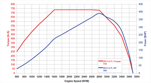
As you see, the power and torque grow relatively monotonically until
some engine limitations start playing significant role. While in the
area of monotonic growth, we can take a particular angular speed, say,
1400 RPM (revolutions per minute) and see that the power of an engine
equals approximately 174 HP (mechanical horsepower) and the torque is
about 650 Lb-Ft (pound-feet).
Let's check if the relationship between power and torque derived above is held in this case.
First of all, we transform all units into standard physical measures defined in SI:
1 RPM (revolutions per minutes) =
= 2π radian per minute =
= 2π/60 radians/sec =
= 0.1048 rad/sec
1 HP = 745.7 W = 745.7 J/sec
1 Lb-Ft = 1.35582 J
Substituting all the above, we see that
angular speed is equal to
1400·0.1048 = 146.6 rad/sec
power is
174·745.7 = 129,751.8 J/sec
torque equals to
650·1.35582 = 881.3 J
Now we can check the relationship between the power, torque and angular speed
P = τ·ω
Indeed,
881.3·146.6 = 129,198.6
As we see, the difference between power and a product of torque by
angular speed is minimal, attributable to imprecise measurement of the
parameters and graph reading.
Tuesday, December 11, 2018
Unizor - Physics4Teens - Mechanics - Work - Problems
Notes to a video lecture on http://www.unizor.com
Problems on Mechanical Work
Problem A
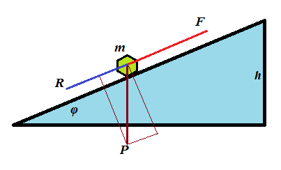
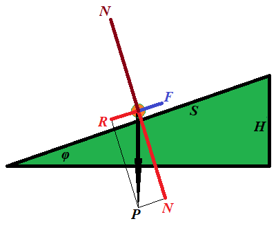
An object of mass m is pushed up a plane inclined to horizon at angle φ with constant acceleration a to a height h against a friction with coefficient of kinetic friction μ.
(a) What is the amount of work necessary to achieve this goal?
(b) Consider the following real conditions of this experiment:
m = 10kg(kilograms)
g = 9.8m/sec²(meters per sec²)
h = 0.5m(meters)
φ = 30°(degrees)
μ = 0.2
a = 0.1m/sec²(meters per sec²)
The work W=F·S is measured in N·m=kg·m²/sec² units, called joule and abbreviated as J.
Calculate the work W performed in this experiments in joules.
Solution
Let F be the force that pushes the object up the slope, P=m·g is the object's weight, R is the force of resistance from the friction, S is the distance this object moves to reach the height h.
(a) F−P·sin(φ)−R = m·a
R = P·cos(φ)·μ
W = F·S
S = h/sin(φ)
F = P·sin(φ) + R + m·a =
= m·[g·sin(φ) + g·cos(φ)·μ + a]
W = F·h/sin(φ) =
=m·h[g+g·cot(φ)·μ+a/sin(φ)]
(b)
W = 67J(joules)
Problem B
An object of mass m is pushed by a constant force F down a slope of a plane inclined to horizon at angle φ. Initially, it's at rest, the final speed is V. There is a friction with coefficient of kinetic friction μ.
(a) What is the time t from the beginning to the end of the object's motion?
(b) What is the distance S this object moved until reaching the final speed V?
(c) What is the amount of work W performed by this force?
(d) Consider the following real conditions of this experiment:
F = 20N(newtons)
m = 10kg(kilograms)
g = 9.8m/sec²(meters per sec²)
V = 0.5m/sec(meters per sec)
φ = 5°(degrees)
μ = 0.7
Calculate the work W performed in this experiments in joules, distance S and time t of motion.
Solution
P=m·g is the object's weight,
R = P·cos(φ)·μ is the force of resistance from the friction,
S is the distance this object moves to reach the speed V,
a is the acceleration of this object.
Then from the Newton's Second Law
F+P·sin(φ)−R = m·a
(we added P·sin(φ) because an object moves down a slope)
Now we can find an acceleration of our object:
F+m·g·sin(φ)−m·g·cos(φ)·μ =
= m·a
a = F/m + g·sin(φ) − g·cos(φ)·μ
Knowing acceleration a and the correspondence between acceleration, final speed and time V=a·t, we can determine time:
(a) t = V/a
Now we can find the distance
(b) S = a·t²/2 = V·t/2
The work performed by the force F equals to
(c) W = F·S
(d) a = 0.066(m/sec²)
t = 7.576(sec)
S = 1.894(m)
W = 37.879(joules))
Problem C
An object of mass m is dropped down from a certain height above a surface of some planet. At the moment it hits the ground its speed is V.
What is the work W performed by the force of gravity?
Solution
Let the acceleration of free falling on this planet is a, the time of falling t and the height S.
Then
F = m·a
V = a·t
t = V/a
S = a·t²/2 = V²/(2·a)
W = F·S = m·V²/2
Notice, the work depends only on mass and final speed - the results of
action, not on the height, nor acceleration of free falling, nor on
time.
Friday, October 12, 2018
Unizor - Physics4Teens - Mechanics - Work - Golden Rule of Mechanics
Notes to a video lecture on http://www.unizor.com
Golden Rule of Mechanics
Let's summarize what we have learned about mechanical work in the previous lecture.
1. In a simple case of motion along a straight line with a constant force F acting along a trajectory, the most important parameter that quantifies the result of the action is work defined as W=F·S, that fully characterizes and is fully characterized by speed V of an object:
W = F·S = m·V²/2
In particular, it means that increasing the force by a factor of N and decreasing the distance it acts by the same factor of N would result in the same final speed of an object.
So, we can "win" in distance, but we will "lose" in force and vice versa.
This is the first example of the Golden Rule of Mechanics - there
are many ways to achieve the result, you can reduce your distance, but
you will have to increase the force or you can reduce the force, but you
will have to increase the distance.
In short, as we mentioned above, whatever you win in distance you lose in force and vice versa.
2. In case of a constant force acting at an angle to a straight line trajectory, the difference is only a factor cos(φ), where φ is an angle between a force and a direction of a trajectory. In vector form it represents the scalar product (F·S).
So, the Golden Rule works exactly as above.
3. Recall the formula for work of a force F pushing an object of weight P up along an inclined plane of the length S making angle φ with horizon to the height H:
W = F·S = P·H
We've proven this in the previous lecture and, as you see, it's
independent of the slope of an inclined plane. However, the minimum
effort we have to apply as a force to move an object up the slope is F=P·sin(φ), while the distance equals to S=H/sin(φ).
We can reduce the effort (the force F) by using an incline of a smaller slope, but that would lengthen the distance S we have to push an object.
So, again, we see the Golden Rule in action.
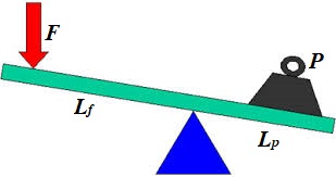
4. Consider lifting some heavy object of the weight P using a lever, applying the force F to the opposite to an object end of the lever.
This is a case of equilibrium in rotational motion and the balance can
be achieved by equating the moments of two forces acting against each
other:
F·Lf = P·Lp
If Sf is the distance the force F acts down and Sp is the distance our object moves up,
Sf/Sp = Lf/Lp and
F·Sf = P·Sp
By using a lever with longer arm Lf for the application of force, we can proportionally reduce the force F
achieving the same result - lifting an object to certain height. An
inverse is true as well - we can shorten the arm and proportionally
increase the force.
In any case, the Golden Rule of Mechanics is observed: "winning"
in force - proportionally "losing" in distance or "winning" in distance"
- proportionally "losing" in force.
All the above examples emphasize the importance of the concept of mechanical work as the quantitative measure and characteristic of the purpose and the result of applying a force. The so-called Golden Rule of Mechanics is just a catchy term that underscores the importance of the concept of work.
Acting with the force to achieve certain goal necessitates performing
certain amount of work that depends on the goal, not on how we achieve
it.
Wednesday, October 10, 2018
Unizor - Physics4Teens - Mechanics - Work - Definition
Notes to a video lecture on http://www.unizor.com
Definition of Mechanical Work
Why do we apply a force to an object?
Usually, to achieve certain result, like to accelerate it to a certain speed or to move it from one point to another.
Straight line motion with a force acting along a trajectory
Consider an acceleration of a car by pressing the gas pedal. As a
result, a car will reach certain speed and then, in absence of the
traffic lights, disregarding friction and air resistance, it goes by
inertia, maintaining this constant speed.
A car with a more powerful engine will need a shorter distance to reach
certain speed. A car with a weaker engine accelerates on a longer
distance to reach the same speed.
It seems, there is some relationship between the force, the distance it
is applied to an object and the final speed reached by this object as a
result of the acting force.
Let's consider the final speed of a constant force F acting on an object of mass m, initially at rest, acting on certain distance S.
The acceleration of this object, according to the Second Newton's Law is
a = F/m
The time t to cover distance S with acceleration a is based on the formula of Kinematics
S = a·t²/2 and is equal to
t = √2S/a = √2S·m/F
From this we derive the final speed at the end of acceleration
V = a·t = (F/m)·√2S·m/F =
= √2F·S/m
As we see, the final speed of an object of mass m depends on the product of the force and the distance this force is acting.
This product that characterizes the result of applying a force on a certain distance is called the work performed by a given force acting on a given distance:
W = F·S
We can reduce by half the force and double the distance - the resulting speed will be the same.
Using this definition of work, we can represent the final speed as
V = √2W/m
Resolving for work as a function of final speed, we obtain
W = m·V²/2
So, given a final speed, we can determine how much work it takes to
achieve it and, given amount of work, we can calculate the speed this
work will cause.
This concept of work is closely tied with such less precisely
defined concepts of result, purpose, effect etc. While we not always can
compare the results or effect of two physical experiments, we can
always compare the work done by the forces participating in these experiments.
Thus, the work can be used to measure the results or effect of physical experiment.
Straight line motion with a force acting at an angle to a trajectory
Consider a slightly more complicated example with force acting at an angle to a trajectory.
A toy train of mass m is pulled by a child, who stands on a side of a track, with a constant force F, so the force acts at an angle to a straight line trajectory, making an angle φ with it.
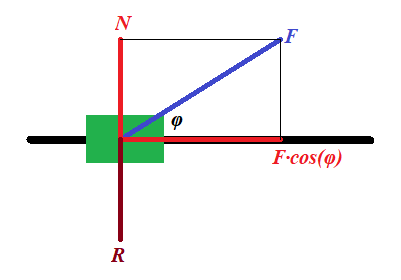
Representing this force F (in blue on a picture above) as a
sum of two forces (in red), one acting along a track, forcing the train
to speed up, and another acting perpendicularly to a track (force N), which is balanced by the reaction of the track R (in brown), we see that the force that pushes a train forward equals to F·cos(φ), while the force acting perpendicularly to a track can be simply ignored as being balanced by an opposite reaction force.
Exactly the same considerations as above leads us to a more universal formula for relationship between the final speed and the work:
V = √2W/m ,
where W = F·S·cos(φ)
Obviously, if the force acts along a straight line of a trajectory, angle φ is zero, its cosine is 1 and the formula corresponds to the one derived earlier.
Resolving the formula above for work, we obtain
W = m·V²/2
which indicates that the work depends on the result of an action
only (final speed), not the way how we achieve this result, using a
stronger force on a shorter distance or a weaker force on a longer
distance.
Motion against gravity along an inclined plane
Let's consider a completely different goal of a physical experiment and show the importance of a concept of work.
This time our purpose is to lift an object of mass m to a certain height H above the ground along a frictionless inclined plane making angle φ with horizon.
The force F needed for this must be equal to a component R of the weight P of an object along the inclined because the other component of its weight N, perpendicular to an inclined, is balanced by a reaction of the plane.
F = P·sin(φ)
The distance S this force is acting on equals to
S = H/sin(φ)
From this we can derive the work performed by force F along the distance S:
W = F·S = P·sin(φ)·H/sin(φ) =
= P·H
This is quite a remarkable result. The work does not depend on the angle of an incline, only on the height we lift the object and its weight.
As in the previous cases, the work seems to be a characteristic
of the result and does not depend on how we have achieved it, using an
inclined with bigger or smaller slope.
Rotational motion with a force acting tangentially to a trajectory
Our final example is about rotation.
Consider a person starts rotating a carousel of a radius r, having a moment of inertia I, from the state of rest to some angular speed ω with constant angular acceleration α, applying constant force F tangentially to the carousel's rim.
From the rotational dynamics we can determine angular acceleration, knowing torque τ of the force and a moment of inertia of a carousel I:
τ = F·r = I·α
α = F·r/I
Linear acceleration of the point of application of the force equals to r·α.
To achieve the final angular speed ω with angular acceleration α we need time
t = ω/α = ω·I/(F·r)
During this time the point of application of force travels around a circle for a distance of
S = r·α·t²/2 =
= r·(F·r/I)·[ω·I/(F·r)]²/2 =
= I·ω²/(2F)
Multiplying by F both sides, we obtain the relationship between work W=F·S and final angular speed achieved as a result of application of the force:
W = F·S = I·ω²/2
This is a rotational equivalent of the analogous formula for straight line movement derived in the beginning of this lecture.
So, given a final angular speed, we can determine how much work it takes
to achieve it and, given amount of work, we can calculate the angular
speed this work will cause.
Definition of work in simple cases presented above
All the above examples provide a proper basis for the following definition of the work:
Work of the force F acting at an angle φ to trajectory on the distance S is
General case of a motion along a curved trajectory
To be more precise and to cover a case of a curved trajectory, we have
to require that this definition should be applied to infinitesimal
amount of work dW performed on infinitesimal interval dS of trajectory:
dW = F·dS·cos(φ)
Using a concept of scalar product of vectors and considering force and interval as vectors, the same definition can be written as
dW = (F ·dS )
The latter represents the most rigorous definition of work.
Wednesday, October 3, 2018
Unizor - Physics4Teens - Mechanics - Statics - Problems
Notes to a video lecture on http://www.unizor.com
Problems on Equilibrium
Problem 1
Two point-objects of mass M and m are hanging at two opposite ends of a weightless rod of length L.
At what point on a rod should we fix a thread, so the system of a rod with two weights is hanging on this thread in equilibrium?
Does this state of equilibrium imply that a rod is horizontal?
Answer
At distance m·L /(M+m) from the end with object of mass M.
Problem 2
An object of weight W is positioned on a flat surface. The coefficient of static friction is μ.
What is the minimum pulling force P to be applied to a
rope, attached to this object, to start pulling it forward, if the angle
between a rope and a horizontal flat surface is φ?
Answer
P = μ·W / [cos(φ)+μ·sin(φ)]
Problem 3
Consider the following illustration to this problem.
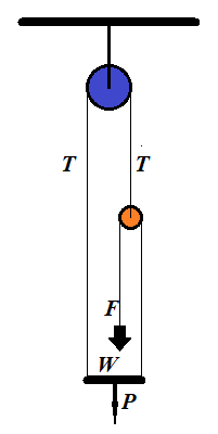
A person of weight W stands on a platform of weight P. Pulleys and ropes are arranged as on this illustration.
What is the force F a person should apply to a rope to keep the whole system in equilibrium?
Solution
Let N be a reaction of a platform onto a person. It pushes the person upward.
If F is a force of a person pulling a rope down, and the
system is in equilibrium, that is all components are at rest and all
forces are balanced, the rope pulls a person up with the same force F, according to the Third Newton's Law.
Since a person is in equilibrium, forces directed upward (N+F) should be equal in magnitude to forces directed downwards (weight of the person W):
N+F = W
The platform is also in equilibrium. The forces that push it down are its weight P and reaction N of a person standing on it. The forces pulling the platform up are tensions of two ropes T on the left and F on the right:
P+N = T+F
Finally, a small pulley is in equilibrium. It's pulled down by two tensions F, from the left and from the right. The tension T pulls it up:
T = 2F
We have three equations with three unknowns: T, N and F, which we have to solve for an unknown force F, with which a person pulls a rope to balance the system:
Substituting T from the last equation into the second one, getting a system of two equations:
N+F = W
P+N = 3F
Solving the first equation for N and substituting into the second:
P+W−F = 3F
Resolving for F:
F = (P+W)/4
Answer
F = (P+W)/4
Problem 4
A ladder is standing at some angle to the floor. It's in equilibrium,
that is it's not slipping down to the floor. What holds it is the static friction between it and the floor.
If the ladder stands almost vertically, the static friction is
greater and it easily holds the ladder in the position. As we move the
bottom of a ladder away from the vertical, there will be a point when static friction will no longer could hold the ladder in place and the ladder would slip down to the floor.
What is the smallest angle the ladder would hold if the coefficient of static friction is μ?
Solution
Consider the following illustration to this problem.
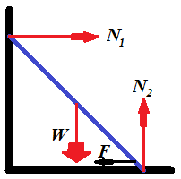
While the reaction of the wall N1 is smaller than the static friction F, the ladder would hold its position.
The smallest angle between the ladder and the floor will be when these two forces are equal.
To be in equilibrium, vector sum of all forces must be equal to
null-vector and a sum of all angular momentums also must be equal to
null-vector.
Along the horizontal X-axis the sum of all forces equals to zero if the horizontal reaction of the wall N1 equals to the force of static friction F, which, in turn, equals to a product of the vertical reaction of the floor N2 by a coefficient of static friction μ:
(a) N1 = μ·N2
Along the vertical Y-axis the sum of forces equals to zero if the reaction of the floor N2 equals to weight of a ladder W:
(b) N2 = W
To analyze angular momentums, let's choose an axis of rotation. It's
easier to choose an axis perpendicular to both X- and Y-axis that goes
through a point where a ladder touches the floor. In this case angular
momentums of forces N2 and F are zero because their corresponding radiuses are zero.
Let's assume that the length of the ladder is D and the angle between the ladder and the floor is φ. The magnitude of the angular momentum of the force of weight W will then be W·D·cos(φ)/2. The magnitude of the angular momentum of the reaction of the wall N1 will be N1·D·sin(φ). The condition of the sum of angular momentums to be equal to zero results in the equation:
N1·D·sin(φ) = W·D·cos(φ)/2
The length of the ladder can be canceled:
(c) N1·sin(φ) = W·cos(φ)/2
Equations (a), (b) and (c) form a system of three equations with three unknowns:
(a) N1 = μ·N2
(b) N2 = W
(c) N1·sin(φ) = W·cos(φ)/2
From this
tan(φ) = 1/(2μ)
Answer
φ = arctan[1/(2μ)]
Interestingly, the answer does not depend on the weight or the length of the ladder.
Wednesday, September 26, 2018
Unizor - Physics4Teens - Mechanics - Statics - Equilibrium of Solids
Notes to a video lecture on http://www.unizor.com
Equilibrium of Solids
As we know, if a vector sum of forces, acting on a point-object, equals
to null-vector, this point-object is at rest or in a state of uniform
motion along a straight line in any inertial frame of reference.
Alternatively, we can say that a frame of reference associated with this
point-object is inertial.
The complexity of a concept of equilibrium of solids lies in the fact
that, even if vector sum of forces, acting on a solid, equals to
null-vector, this solid might not be in the state of rest in any
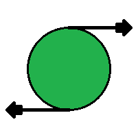
inertial system. In a simple case of two forces, equal in magnitude and
opposite in direction, applied to two different points of a solid, will
rotate it, making a frame of reference associated with it non-inertial.
Any rotation of a solid, however complex, can be represented as a
combination of three rotations around three coordinate axes. Therefore, a
solid in a state of equilibrium should be in equilibrium relative to
each coordinate axis, and, to study equilibrium of a solid in
three-dimensional space, it is sufficient to study it relative to one
axis.
As we know, in case of rotation around an axis, the main factor replacing a concept of force for translational movement, is torque. Since torque is a cause of rotation, the necessary condition to prevent a rotation is balancing of torques.
Torque is a vector equal to a vector (cross) product of a radius-vector r from the axis of rotation to a point of application of force (perpendicularly to the axis) by a vector of force:
τ = r×F
Using this concept of torque, we can formulate the following necessary condition for an equilibrium of a solid.
Sum of torques of all forces acting on a solid relative to each coordinate axis must be equal to null-vector.
In the previous lecture we introduced a concept of a degree of freedom
and, in particular, mentioned six degrees of freedom of a solid: three
degrees of freedom along each coordinate axis and three degrees of
freedom of rotation around each coordinate axis.
If a vector sum of all forces acting on a solid is a null-vector, there
will be a point that is not moving anywhere or, more precisely, a frame
reference associated with this point is inertial. This condition assures
an equilibrium by three degrees of freedom associated with
translational motion (a motion along coordinate axes).
If a vector sum of all torques relatively to each of the three
coordinate axes is a null-vector, there will be no rotation and the
system will be in equilibrium by three other degrees of freedom
associated with rotational motion (a motion around coordinate axes).
So, for a solid to be in equilibrium, the necessary conditions are
all of the above - sum of all the forces and sum of all the torques must
be null-vectors.
Consider the following example.
A weightless rod of a length 2r is hanging horizontally on a thread fixed at its midpoint.
On both ends of a rod there are equal weights W hanging down.
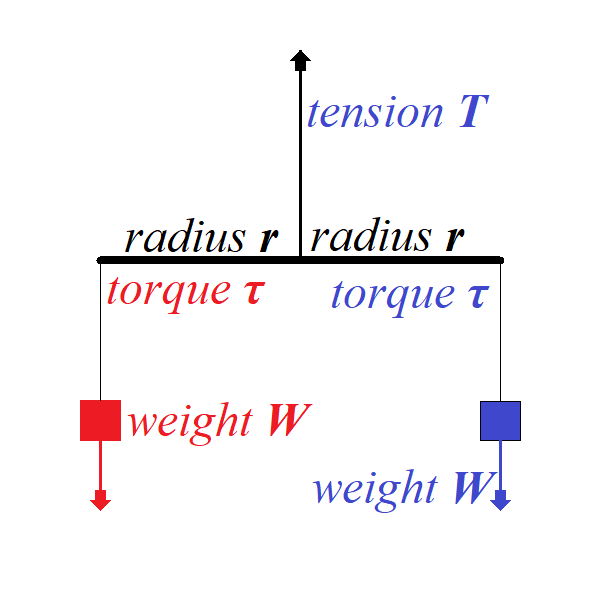
To balance the translational movement of a system vertically down the force of tension T on a thread that holds the rod must balance a sum of forces of weight acting in opposite direction:
T + W + W = 0
T = −2W
To balance the rotational movement of a system around a midpoint of a
rod the torque of one weight should be equal in magnitude to the torque
of another weight since the directions of these two torques are
opposite:
τ blue = r ×W
τ red = −r ×W
τ red + τ blue = 0
Consider a less symmetrical case below.
Here a rod of the length 3r is hanging by a thread fixed not in the middle, but at a distance r from the left edge and, therefore, at a distance 2r from the right edge.
At the same time, the weight on the left is twice as heavy as the one on the right.
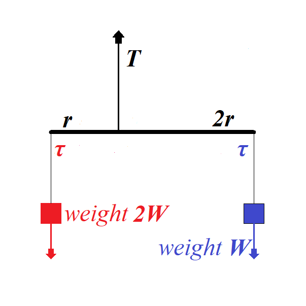
Tension on the thread holding a rod must be greater to hold more weight:
T + W + 2W = 0
T = −3W
From the rotational viewpoint, this system is in equilibrium because the
torques on the left of a rod and on the right are equal in magnitude,
while opposite in direction:
τ blue = 2r ×W
τ red = −r ×2W
τ red + τ blue = 0
Thursday, September 20, 2018
Unizor - Physics4Teens - Mechanics - Statics - Point-Objects
Notes to a video lecture on http://www.unizor.com
Equilibrium of Point-Objects
The state of equilibrium in a case of possibility of a
point-object to move in some direction implies that the position of this
object does not change, which, in turn, implies that the vector sum of
all forces acting on it is a null-vector:
ΣFi = 0 .
In three-dimensional world each force Fi
has three components - the projections of this force on X-, Y- and
Z-axis. In order for a sum of vectors to be equal to a null-vector, it
is necessary and sufficient for a sum of their X-components to be equal
to 0, same for Y- and Z-components.
Therefore, we can construct three equations, one for each axis, to determine forces participating in the state of equilibrium:
ΣFi(x) = 0
ΣFi(y) = 0
ΣFi(z) = 0
The fact that only three equations determine the conditions on forces to
be in equilibrium in a three-dimensional world means that unique
determination of these forces is possible only if the number of unknowns
does not exceed three. If four or more unknown variables participate in
the state of equilibrium, we will have infinite number of solution of
the system of three linear equations with four or more unknowns.
Most likely, for our purposes we will consider situations with only unique solutions.
As a simple example of an equilibrium in three-dimensional space,
consider a chandelier of some weight hanging from a ceiling on three
threads attached to a ceiling at three different points. For simplicity,
assume that a chandelier is a point-object and three points of
attachment of the threads to a ceiling are making an equilateral
triangle and the length of all threads is the same.
The weight of a chandelier W is balanced by three equal in magnitude T,
but acting at different angles, tension forces along each thread.
Knowing the weight of a chandelier and an angle of each thread with a
vertical φ (the same for each thread in our simple case), we can easily determine the magnitude of the tension force of each thread:
3·T·cos(φ) = W
T = W / [3·cos(φ)]
Here we only constructed the equation along the vertical Z-axis because
in a horizontal plane (along X- and Y-axis) the tension forces balance
each other.
The example above is a perfect illustration to our next discussion.
Stable Equilibrium
We call an equilibrium stable if, after a small movement of an object from its position of equilibrium, it returns back to this position.
A small push of a chandelier will result in its light swinging and eventual return to the original position of equilibrium.
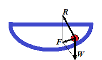
Consider a cup in a form of semi-sphere and a small ball at the bottom of this cup. It lies in the state of stable equilibrium. If we push it off this position, it will eventually return back because the sum F of reaction force R of the cup and the weight W of a ball always act in a direction of the lowest point of this semi-spherical cup.
Let's formulate the definition of a stable equilibrium in more precise terms.
For this we have to consider a position of an object in equilibrium and
its immediate neighborhood. Since we consider the equilibrium to be
stable, we have to consider the deviation of an object from a position
of equilibrium.
Basically, we would like to say that the equilibrium is stable, if an
object returns to it from any neighboring point. How big is the
neighborhood, from which this return takes place is, obviously, a
subject of a definition.
The rigorous definition of a stable equilibrium defines the neighborhood as any, however small, one.
So, if exists a real positive value ε such that from any point within ε-neighborhood
of a position of equilibrium an object, placed at this point, returns
to a position of equilibrium, the equilibrium is stable.
Unstable Equilibrium
The unstable equilibrium is the opposite of a stable one. That
means that any, however small, deviation of the object's position from
the position of equilibrium results in moving of this object away from
the equilibrium point.
Obvious example is a small ball on the top of a sphere. If its position
is exactly at the North Pole, it's in equilibrium. But any, however
small, deviation from the NorthPole results in complete departure from
the position of equilibrium.
Neutral Equilibrium
Consider a ball on a horizontal plane. There are two forces acting on it
- gravity vertically down and reaction of the plane vertically up and
equal in magnitude to the ball's weight. These two forces neutralize
each other, no matter where on the plane our ball is positioned. So, any
position is a position of equilibrium. This is exactly what neutral equilibrium is.
Any deviation from the position of neutral equilibrium results in the new equilibrium.
Strictly speaking, neutral equilibrium implies existence of some
neighborhood around the position of equilibrium such as any position
within this neighborhood is a position of equilibrium.
Solids and Six Degrees of Freedom
Before we talked about equilibrium of a point-object, that is a state of
rest, when all forces applied to it are in balance and their sum is
null-vector.
Let's expand our concept of equilibrium to solids. Obviously, they not
only can move in three different directions (forward-backward along
X-axis, left-right along Y-axis, up-down along Z-axis), but also can
rotate around any of the three coordinate axis.
That means that a position of a solid is determined by six parameters - so called six degrees of freedom. Equilibrium of this solid object implies its state of rest along each of these six degrees of freedom.
We know how to deal with the first three degrees of freedom associated with translational motion.
Conditions of equilibrium related to rotation - the other three degrees of freedom - will be analyzed in the next section.
Thursday, September 6, 2018
Unizor - Physics4Teens - Mechanics - Rotational Dynamics - Conservation ...
Notes to a video lecture on http://www.unizor.com
Conservation of
Angular Momentum
We ended up the previous lecture deriving the Law of Conservation of
Angular Momentum. In this lecture we will continue discussing this
particular conservation law.
We will consider a thought experiment suggested by Arkady Kokish in our private discussion of this topic.
The results of this thought experiment will confirm the Angular Momentum Conservation Law.
Consider a point-object of mass M with no external forces (like gravity) present and two threads, short of length r and long of length R tied to it.
A person holds both threads and starts spinning an object with angular velocity ω1. It will rotate along a circular trajectory of a radius r (the length of a shorter thread).
Let's analyze what happens if this person lets a shorter thread go, while holding the long one.

On the picture above the short thread is let go when an object was at
the top. Then, since nothing holds it on a circular trajectory, it will
fly along a tangential line maintaining the same linear speed it had
when it was rotating, that is r·ω1.
But our object will not fly too far. The longer thread will stop it, when it will be on a distance R from a center of rotation.
Here is a picture of this particular moment, when the long thread is fully extended.
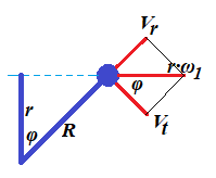
At this moment the linear speed of an object flying (on the picture) left to right equals to V=r·ω1.
Let's represent this vector as a sum of two vectors: Vt perpendicular to a line representing the fully extended long thread (tangential to a future circular trajectory of a radius R) and Vr going along that thread line (radial).
Assuming an angle between a short thread at a moment it was let go and a
long one at the moment it is fully extended, stopping tangential
movement of an object, is φ, it is obvious that r=R·cos(φ).
At the moment when the long thread is fully extended the tension of the
thread instantly (actually, during a very short interval of time Δt) nullifies the radial speed Vr. To be exact, its moment of inertia M·Vr will be equal to an impulse of the tension force T during interval of time Δt:
T·Δt = M·Vr
This tension force decelerates the radial speed to zero during the interval of time Δt. The shorter this interval - the more ideal our experiment is.
In an ideal case of non-stretchable thread that can withstand infinite tension the interval Δt is infinitely small, and deceleration is infinitely large in magnitude and short in time.
In this case the radial speed Vr will be brought down to zero instantaneously.
At the same time the magnitude of tangential vector of speed Vt is not affected by the tension since this vector is perpendicular to a tension force.
We see that the angle between vectors V=r·ω1 and Vt is the same as between threads φ.
Therefore, Vt = r·ω1·cos(φ)
But cos(φ) = r/R
from which follows
Vt = r·ω1·r/R
Tangential linear speed Vt is related to angular speed of rotation ω2 of our object on a new radius R as Vt=R·ω2.
Hence,
R·ω2 = r·ω1·r/R
R²·ω2 = r²·ω1
M·R²·ω2 = M·r²·ω1
Expression M·r² represents the moment of inertia I1 of an object of mass M rotating on a radius r.
Analogously, expression M·R² represents the moment of inertia I2 of the same object of mass M rotating on a radius R.
Therefore, we have derived the Law of Conservation of the Angular Momentum:
I1·ω1 = I2·ω2
Monday, August 27, 2018
Unizor - Physics4Teens - Mechanics - Rotational Dynamics - Problems
Notes to a video lecture on http://www.unizor.com
Problems on
Rotational Dynamics
Problem 1
Consider a device that consists of a wheel of radius r and mass M, freely rotating on some fixed axis, a thread rolled around it a few times and a point-object of mass m hanging off that thread.
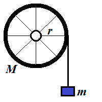
Assume that all mass of a wheel is concentrated in its rim, while spokes are weightless.
There is no friction in the rotating wheel.
A thread is weightless and unstrechable.
The force of gravity pulls the object down with free fall acceleration g.
What will be the acceleration of an object?
Solution
The weight of a wheel is balanced by the reaction of fixed axis and, therefore, can be ignored.
The only force acting tangentially on a wheel is the tension of a tread T trying to rotate it.
Therefore, we can equate its momentum τ=T·r (torque) to a product of its moment of inertia I and angular acceleration α:
τ = T·r = I·α
The fact that all mass of a wheel is concentrated in its rim allows us
to easily calculate its moment of inertia. We can imagine a rim
consisting of a large number N of point-objects of mass M/N each. The moment of inertia of each is (M/N)·r² and combined moment of inertia of a wheel is N·(M/N)·r²=M·r². If the mass is not concentrated in the rim, analogous logic would lead us to more involved calculations of inertial mass.
Considering, I=M·r² and r·α=a (where a is a linear acceleration of a thread) we can write the following equation:
T·r = M·r²·a/r = M·r·a
Radius cancels out and we get
T = M·a
Notice that this is exactly the same equation as the Newton's Second Law, as if an object of mass M is pulled along a straight line by a force T with linear acceleration a.
Another important detail is that this formula is independent of a radius
of a wheel - a direct consequence of the fact that the mass of a wheel
is concentrated in its rim.
Analyzing the movement of an object hanging on a thread, we conclude that it moves with linear acceleration a down by the forces of gravity (directed down) and tension of a thread (directed up). Therefore, using the Newton's Second Law,
m·g − T = m·a
Now we have a system of two equations with two unknowns T and a, which is easy to solve.
Substitute T from the first equation to the second:
m·g − M·a = m·a
m·g = (M + m) · a
a = m·g / (M + m)
Problem 2
Calculate a moment of inertia of disk of mass M and radius R rotating around an axis going through its center perpendicularly to its surface.
Solution
Divide a disk into a set of concentric rings of infinitesimal width dr. Let the inner radius of a particular ring be r and it outer radius be r+dr.
Moment of inertia of each ring is
I(r) = m·r²
where m is its mass (see the previous Problem 1 for explanation).
Mass of a ring m is a mass of a disk M multiplied by a ratio of a ring's area 2πr·dr to the area of an entire disk πR².
So, the moment of inertia of our ring of radius r and infinitesimal width dr is
I(r) = [M·2πr·dr/(πR²)]·r²
Integrating this from r=0 to r=R, we get
Idisk(M, R) =
= ∫[M·2πr·dr/(πR2)]·r2 =
= (2M/R2)∫r3dr =
= (2M/R2)·(r4/4) =
= M·R2/2
Problem 3
Consider Problem 1, but change a wheel with all mass concentrated in the
rim with a wheel with mass evenly distributed inside the circumference,
making it a disk.
Solution
We follow the same logic as in Problem 1.
The weight of a wheel is balanced by the reaction of fixed axis and, therefore, can be ignored.
The only force acting tangentially on a wheel is the tension of a tread T trying to rotate it.
Therefore, we can equate its momentum τ=T·r (torque) to a product of its moment of inertia I and angular acceleration α:
τ = T·r = I·α
The fact that all mass of a wheel is evenly distributed within its
circumference allows us to easily calculate its moment of inertia using
the Problem 2 above:
I=M·r²/2
Linear acceleration a and angular acceleration α are related:
r·α=a
Therefore,
T·r = [M·r²/2]·(a/r) = M·r·a/2
Radius cancels out and we get
T = M·a/2
An important detail is that this formula is independent of a radius of a wheel.
Analyzing the movement of an object hanging on a thread, we conclude that it moves with linear acceleration a down by the forces of gravity (directed down) and tension of a thread (directed up). Therefore, using the Newton's Second Law,
m·g − T = m·a
Now we have a system of two equations with two unknowns T and a, which is easy to solve.
Substitute T from the first equation to the second:
m·g − M·a/2 = m·a
m·g = (m + M/2) · a
a = m·g / (m + M/2)
If we compare this formula with the one in Problem 1, we see that final acceleration is greater because denominator is smaller.
So, the disk in this problem will rotate faster than a wheel with empty middle part from Problem 1.
Problem 4
Let's rotate a small ball of mass M within a horizontal plane on a thread of length D. The thread will make certain angle φ with the horizon. Experiments show that the angle will be smaller if a ball rotates faster.
Determine the relationship between angular speed of rotation ω, mass of a ball M, length of a thread D and angle φ, ignoring friction and air resistance.
Solution
The tension of a thread T keeps a ball on its orbit. Radius of an orbit is R=D·cos(φ).
The tension of a thread T serves dual purpose - its vertical component T·sin(φ) acts against gravity M·g, its horizontal component T·cos(φ) acts as a centripetal force and should be equal to M·V2/R, where V is a linear speed of a ball, which is equal, in turn, to R·ω, where ω is angular speed of rotation of a ball.
So, we have the following equations:
T·sin(φ) = M·g
T·cos(φ) = M·(V2)/R = M·R·ω2 = M·D·cos(φ)·ω2
The second equation is simplified to
T = M·D·ω2
Substituting it to the first equation,
D·ω2·sin(φ) = g
Therefore,
sin(φ) = g/[D·ω2]
For a given angular speed we can find an angle of a thread to horizon φ. It in inversely proportional to a length of a thread D and to a square of angular speed ω, which seems to be reasonable.
Interestingly, this angle is independent of the mass M.
Tuesday, August 21, 2018
Unizor - Physics4Teens - Mechanics - Dynamics - Angular Momentum
Notes to a video lecture on http://www.unizor.com
Angular Momentum
Recall the rotational equivalent of the Newton's Second Law:
τ = I·α
where
τ = F·r - a torque, a product of tangentially applied force F and the distance from the point of application of force to the axis of rotation r;
I = m·R² - a moment of inertia, a product of inertial mass of a point-object by a square of its distance from the axis of rotation R (might be different from the distance r above);
α - angular acceleration of rotation.
It is very important to correspond straight line translational elements of motion with their rotational counterparts:
| Translation | Rotation |
| Force F | Torque τ = F·r |
| Linear Acceleration a | Angular Acceleration α = a/r |
| Inertial Mass m | Moment of Inertia I = m·r² |
| Newton's Second Law F=m·a | Rotational Equivalent τ = I·α |
Now we will consider a rotational equivalent of a familiar equation
between impulse and momentum in translational motion along a straight
line.
As is known from the previous material, there is a correspondence between these quantities: impulse of the force F exhorted during an infinitesimal time period dt equals to an increment of the momentum d(m·v), where m is mass and v - velocity of an object:
F·dt = d(m·v)
Let's see if the corresponding rotational characteristics of motion have similar dependency.
We know the rotational equivalent of the Newton's Second Law τ=I·α.
Multiplying it by dt, we obtain
τ·dt = I·α·dt
Since a product of angular acceleration α and infinitesimal time interval dt is an infinitesimal increment of angular speed dω, there is an equality
τ·dt = I·dω = d(I·ω)
The latter fully corresponds to an equation between impulse and momentum
of translational movement. It represents the relationship between rotational impulse τ·dt of torque τ during time interval dt and increment of rotational (angular) momentum d(I·ω) of an object with a moment of inertia I and angular speed ω.
We can continue our table of correspondence between translational motion
along a straight line and rotation along a circular trajectory.
| Translation | Rotation |
| Impulse F·dt | Rotational Impulse τ·dt |
| Momentum d(m·v)=F·dt | Rotational Momentum d(I·ω)=τ·dt |
Trivial consequence of an equation
τ·dt = d(I·ω)
is that
τ = d(I·ω)/dt = (I·ω)'
From this follows that if the balance of all torques acting on an object is zero, the rotational momentum remains constant.
This is the Law of Conservation of the rotational (angular) momentum.
Monday, August 20, 2018
Unizor - Physics4Teens - Mechanics - Dynamics - Moment of Inertia
Notes to a video lecture on http://www.unizor.com
Moment of Inertia
Recall the rotational equivalent of the Newton's Second Law:
τ = I·α
where
τ = F·r - a torque, a product of tangentially applied force F and the distance from the point of application of force to the axis of rotation r;
I = m·R² - a moment of inertia, a product of inertial mass of a point-object by a square of its distance from the axis of rotation R (might be different from the distance r above);
α - angular acceleration of rotation.
It is very important to correspond straight line translational elements of motion with their rotational counterparts:
| Translation | Rotation |
| Force F | Torque τ = F·r |
| Linear Acceleration a | Angular Acceleration α = a/r |
| Inertial Mass m | Moment of Inertia I = m·r² |
| Newton's Second Law F=m·a | Rotational Equivalent τ = I·α |
In this lecture we will study the moment of inertia and its properties. We will also calculate the moment of inertia in a few simple cases.
The first very important property of the moment of inertia is that it is additive.
It means that the moment of inertia of two rigidly connected
point-objects rotating around the same axis of rotation equals to sum of
their individual moments of inertia.
Let's explain why.
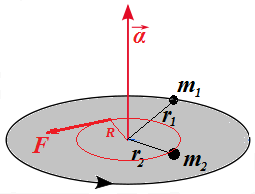
Consider a rigid weightless disk rotating around an axis going through
its center perpendicularly to it and two point-objects of mass m1 and m2 fixed on its surface at distances, correspondingly, r1 and r2.
Assume that this disk with both fixed on it objects is rotating with angular acceleration α caused by some force F acting on a distance R from its center tangentially to a circle of a radius R within a plane of this disk.
The picture below illustrates this.
Our purpose is to explain that the combined moment of inertia of both objects equals to a sum of their corresponding individual moments of inertia.
The fact that object of mass m1 on a distance r1 from the axis of rotation has angular acceleration α implies that there is a force f1 acting on it tangentially to its trajectory such that (from rotational equivalent of the Newton's Second Law):
f1·r1 = I1·α
where I1=m1·r1² - moment of inertia of this object.
Similarly, the fact that object of mass m2 on a distance r2 from the axis of rotation has angular acceleration α implies that there is a force f2 acting on it tangentially to its trajectory such that (from rotational equivalent of the Newton's Second Law):
f2·r2 = I2·α
where I2=m2·r2² - moment of inertia of this object.
Behavior of this system depends only on parameters specified above -
masses, distances from the center of a disk and forces. So, if we change
the initial position of masses without changing their distances from
the center, the system will work exactly the same.
Our first modification then will be to shift the position of mass m2 along its circular trajectory of radius r2 to a position, where it is on the same radius as m1. So, both masses and a center of a disk are on one line.
Similarly, let's shift the point of application of force F to a point on the same line where our two objects are now located without changing the distance R
from the point of application of the force to a center. Now both masses
and a point of application of main force that rotates the disk are on
the same line with a center of the disk, while their distances from a
center are still the same as before.
As we know, the angular acceleration of a rotating object depends on its
mass, its distance from an axis of rotation and a torque of a force
rotating this object.
If force f1 applied directly to an object of mass m1 located on a distance r1 from the axis of rotation caused the angular acceleration α, any other force having the same torque τ1=f1·r1 would result in the same angular acceleration.
Let's replace then the force f1 acting on a distance r1 from the axis with force g1=f1·r1/R, acting on a distance R at the point where our main force F was applied. There will be no change in angular acceleration since the torque acting on our object is the same:
τ'1 = (f1·r1/R)·R = f1·r1 = τ1
Same trick with the second object results in using force g2=f2·r2/R, acting on a distance R at the point where our main force F was applied, with no change in the behavior of the system.
τ'2 = (f2·r2/R)·R = f2·r2 = τ2
We have brought all forces (g1, g2 and F)
to the same point of application. They act in the same direction -
tangentially to a circular trajectory. We know that the effect of main
force F applied to this point is equivalent to a combined effect of forces g1=f1·r1/R and g2=f2·r2/R applied to the same point in the same direction. Therefore, sum of forces g1 and g2 must be equal to force F:
g1 + g2 = F
Now what remains is simple algebra.
f1·r1/R + f2·r2/R = F
f1·r1 + f2·r2 = F·R
τ1 + τ2 = F·R
I1·α + I2·α = F·R
(I1 + I2)·α = F·R
The expression on the right is the torque of the main force F acting tangentially to a circle of rotation on a distance R from the axis:
τ = F·R
Therefore, the expression on the left, according to rotational equivalent of the Newton's Second Law, must be a moment of inertia of the entire system I multiplied by the system's angular acceleration α:
I·α = τ = F·R
from which follows the equality
I·α = (I1 + I2)·α
and, finally,
I = I1 + I2
That means that the combined moment of inertia of two objects equals to a sum of their individual moments of inertia.
In short, moment of inertia is additive.
The most important consequence of this is that, to calculate a moment of
inertia of a rotating solid object of some complicated geometric shape,
we can divide it in small (strictly speaking, infinitesimally small)
pieces, calculate a moment of inertia of each piece and add all these
moments of inertia together (strictly speaking, integrating them) to get
a moment of inertia of the whole rotating solid object.
Let's calculate a moment of inertia of some solids, using this approach.
1. Rod rotating around its edge
Consider a solid thin rod of a length L and mass m rotating around an axis that is perpendicular to it and going through its one end.
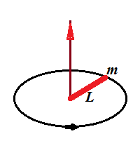
To calculate its moment of inertia, we divide it in small pieces of the length dr, located on a distance r from the axis and having mass dm=(m/L)·dr.
Each such piece has a moment of inertia
dI = (dm)·r² = (m/L)·r²·dr
Since moment of inertia is additive, all we have to do now is to integrate this by r from 0 to L.
The indefinite integral of function r² is r³/3. So, by Newton-Leibniz formula the result of integration on an interval [0,L] is
L³/3 − 0³/3 = L³/3.
So, the total moment of inertia of a rod is
Irod = (m/L)·L³/3 = m·L²/3
2. Rod rotating around its center
Let's calculate the moment of inertia, if the rod rotates around its center point.
We can consider now this rod as a system of two small half-rods, each being a half of the original one, with length L/2 and mass m/2.
Each half-rod rotates around its end, so the formula above is applicable to each half-rod.
Its moment of inertia is
Ihalf = (m/2)·(L/2)²/3 = m·L²/24
The whole rod, being a system of two half-rods, has a momentum of
inertia equal to a sum of momentums of its two halves, so its value is
double of the above moment of inertia for each half-rod:
Iwhole = m·L²/12
Wednesday, August 15, 2018
Unizor - Physics4Teens - Mechanics - Rotational Dynamics
Notes to a video lecture on http://www.unizor.com
Torque
So far we were mostly considering translational motion of point-objects - a motion along a straight line with or without external forces
acting upon this object. We have specified three Newton's Laws of this
motion and derived a lot of interesting facts based on these laws.
Let's recall these laws.
The Newton's First Law is the familiar Law of Inertia that states that
an object at rest stays at rest and an object in uniform motion stays in
this uniform motion, unless acted upon by unbalanced forces.
The Newton's Second Law brings quantitative relationship to vector of force (F), mass (m) and vector of acceleration (a):
F = m·a
The Newton's Third Law states that for every action there is an equal in magnitude and oppositely directed reaction.
Rotational motion obeys the rules in many respects analogous to the laws of translational motion, except we have to change linear movement to rotation, which, in essence, is an angular movement with constant radius.
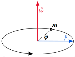
Consider a point-object of some mass m connected by a weightless rigid rod of the length r to an axis, around which this object can rotate within a plane of rotation that is perpendicular to an axis of rotation.
The picture below illustrates such a movement and also indicates the position of angular velocity ω
of a rotation, which was explained earlier, when we studied the
Kinematics of rotation (we assume your familiarity with this topic and
strongly recommend to refresh it before proceeding any further).
Let's discuss the similarities and differences between translational movement along a straight line and rotation around an axis within a plane of rotation perpendicular to this axis.
Obviously, the time concept remains the same in both types of motion.
There is a clear rotational analogy to the Newton's First Law.
An object at rest stays at rest and an object in uniform rotation
stays in this uniform rotation, unless acted upon by unbalanced forces.
The Newton's Third Law is not really specific for a form of motion, so there is no need to address it separately at this moment.
The Newton's Second Law requires certain modification to be applied to rotation.
Let's address the main concept of Dynamics - the force - in connection to rotation.
The very important characteristic of force in Dynamics of translational movement along a straight line is that it can be measured by its effect on objects of certain inertial mass. Thus, a measure of force that gives linear acceleration of
The same force applied to different objects of the same inertial mass will cause the same linear acceleration etc.
The situation with rotational movement is not the same.
Consider a simple experiment of opening a door. If you apply a force to
open a door at its edge opposite to hinges, where the handle is usually
located, it opens relatively faster than if you apply exactly the same
force in the middle of a door. The closer a point of application of the
same force to hinges - the slower a door opens, if the force applied to
it is the same. In an extreme case, when we apply the pressure where the
hinges are, a door will not open at all.
As a continuation of this experiment, if we want to achieve the same
speed of the opening of a door by applying the force at different
distances from the hinges, we need more efforts for a point of force
application located closer to the hinges.
We can measure the force, the distance from the hinges of a point of application of this force and an angular acceleration of the door and experimentally come up with the fact that for the fixed force the angular acceleration of the door is proportional to the distance of a point of application of the force from the hinges.
Moreover, leaving the point of application of the force the same and changing the force, we can determine that angular acceleration is proportional to the force.
What it means is that in a case of rotation a force by itself does not
determine the final motion of a rotating object. It's a product of a
force F and radius to a point this force is applied r, that determines the final effect. This product
| Translation | Rotation |
| Force F | Torque τ = F·r |
Returning to a picture above, we can apply some force F to
any point on the rigid rod, connecting our point-object to an axis of
rotation, directing this force perpendicularly to the rod, and observe
that the resulting angular acceleration of the object is proportional to
both the force F and the distance r from the axis to a point of application of this force, thus proportional to torque
Now we have concluded that an angular acceleration α of rotational motion is proportional to a torque τ. This is analogous to linear acceleration a of translational motion being proportional to a force F. The coefficient of proportionality for translational motion is inertial mass m of an object (this is the Newton's Second Law F=m·a).
The obvious question is, what is the coefficient of proportionality between angular acceleration and torque?
Answer to this question will result in rotational equivalent of the Newton's Second Law.
We have experimentally established that equal torques produce equal angular accelerations.
Consider a rotation illustrated on the picture above. Assume that the point of application of force F is exactly at the point-object of mass m rotating around an axis at a distance r
from it on a rigid weightless rod. Assume further that our force acts
within a plane of rotation and directed perpendicularly to the rod.
During an infinitesimal time interval dt the motion of an object can be considered as linear and, therefore, the Newton's Second Law can be applied, giving F=m·a.
Now we can express it in terms of angular acceleration and torque as follows:
a = r·α
τ = F·r
Hence,
F·r = (m·a)·r = m·r²·α
Finally,
τ = (m·r²)·α
One more logical step is needed. We started from a force applied on an object itself at a distance r
from an axis. But we have experimentally established that equal torques
produce equal actions. It means that some other force applied to some
other point will produce the same effect, causing the same angular
acceleration, as long as the torque is the same.
So, the equality τ=(m·r²)·α is universal, regardless of point of application of force since it depends not on force, but on torque.
The above equality represents the rotational analogue of the Newton's Second Law.
Some generalization can be applied to the above.
What if the force, acting within a plane of rotation, is not perpendicular to a rod?
Obvious solution is to replace vector F
with its projection onto a line on the rotation plane that is
perpendicular to a radius and to multiply the product of two scalars F·r by a sine of an angle between corresponding vectors, effectively using a vector product F⨯r.
So, more general definition of a torque is a vector (or, more precisely, pseudo-vector)
τ = F⨯r
whose direction, like a direction of an angular acceleration, is along an axis of rotation.
So, for rotational movement the vectors of torque τ and angular acceleration α are collinear, similarly to collinearity of vectors of force F and linear acceleration a for translational movement.
We'd like to note that for purposes of simplicity in this course we will
rarely deal with forces not perpendicular to a radius of rotation.
IMPORTANT TERMINOLOGY POINTS
1. The torque τ is often called the moment of force.
2. Recall the expression tying together a torque τ and an angular acceleration α
τ = (m·r²)·α
The expression m·r² is called moment of inertia, is symbolized by letter I, which allows to specify the formula above as
τ = I·α
where I=m·r² is a moment of inertia, playing the same role in this equation as inertial mass m in the Newton's Second Law and representing resistance to a rotational force.
| Translation | Rotation |
| Force F | Torque τ = F·r |
| Acceleration a | Angular Acc. α = a/r |
| Inertial Mass m | Moment of Inertia I = m·r² |
| Newton's Second Law F=m· | Rotational Equivalent τ = I·α |
Subscribe to:
Posts (Atom)
