Sunday, November 22, 2020

AC Power: UNIZOR.COM - Physics4Teens - Electromagnetism - AC Ohm's Law

Notes to a video lecture on http://www.unizor.com

AC Power

Power is a rate of work performed by some source of energy (like electric current) per unit of time. More precisely, it's a derivative of work performed by a source of energy, as a function of time, by time.

As we know from the properties of a direct electrical current, its power is
P = U·I = I²R = U²/R
where U is the voltage around a resistor of resistance R and I is the electric current going through this resistor.
All values in the above expression are constant for direct current.

Alternating current presents a problem of having the voltage and the current to be variable and dependent not only on the resistors, but also on the presence of inductors and capacitors in the circuit.

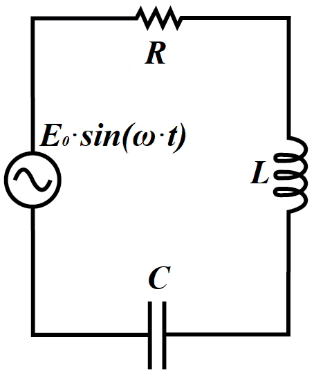
As described in the previous lecture, the alternating current in the circuit of a resistor, an inductor and a capacitor connected in a series to a generator of sinusoidal EMF equals to
I(t) = (E0 /Z)·sin(ωt+φ) =
= I0·sin(ωt+φ)

where impedance Z=√(XC−XL)²+R²,
tan(φ)=(XC−XL)/R.

Having expressions for generated EMF E(t)=E0·sin(ωt) and electric current in a circuit I(t)=I0·sin(ωt+φ), we can find an instantaneous power
P(t) = E(t)·I(t) =
= E0·I0·sin(ωt)·sin(ωt+φ)


When people talk about voltage or amperage in the AC circuit, they understand that these characteristics are variable and, to be more practical, they use effective voltage Eeff = E0 /2 and effective amperage Ieff = I0 /2 of the electric current. The usage of these characteristics allows to calculate the power consumed by a resistor-only circuit during a period [0,T] of time (for T significantly greater than one oscillation of a current) without integrating a variable function P(t)=E(t)·I(t) on interval [0,T], but just performing a multiplication of constants:
W[0,T] = Eeff · Ieff · T

Adding an inductor and a capacitor brings some complication because of a phase difference between EMF and a current. To express the power consumed by an AC circuit that includes a resistor, an inductor and a capacitor in terms of effective voltage and effective amperage, let's find the work performed by an electric current during a period of oscillation in terms of Eeff and Ieff and divide it by this period. The result would be an average power consumed by a circuit per time of one oscillation that we will call the effective power of a circuit.

The period of one oscillation with angular speed ω is T=2π/ω.
The instantaneous power consumption by a circuit is
P(t) = E(t)·I(t) =
= E0·sin(ωt)·I0·sin(ωt+φ)

The energy consumed by a circuit during one period of oscillation T=2π/ω equals to
W[0,T] = [0,T]P(t)·dt
where
P(t)=E0·sin(ωt)·I0·sin(ωt+φ)

We can simplify the product of two trigonometric functions to make it easier to integrate:
sin(x)·sin(y) =
= (1/2)·
[cos(x−y)−cos(x+y)]
Using this for x=ωt and y=ωt+φ, we obtain
sin(ωt)·sin(ωt+φ) =
= (1/2)·
[cos(φ)−cos(2ωt+φ)]

To find the power consumption during one period of oscillation T, we have to calculate the following integral
W[0,T] = [0,T]P(t)·dt
where period T=2π/ω and
P(t) = E0·I0·
·(1/2)·
[cos(φ)−cos(2ωt+φ)]

This integral can be expressed as a difference of two integrals
[0,T]E0·I0·(1/2)·cos(φ)·dt
which, considering cos(φ) is a constant for a given circuit, is equal to
E0·I0·(1/2)·cos(φ)·T =
= E0·I0·(1/2)·cos(φ)·2π/ω

and
[0,T]E0·I0·(1/2)·cos(2ωt+φ)·dt
which is equal to zero because integral of a periodical function cos(x) over any argument interval that equals to one or more periods equals to zero.
The same can be proven analytically
[0,T]cos(2ωt+φ)·dt =
= sin(2ωt+φ)/(2ω)|[0,T] =
= sin(2ω·2π/ω+φ)/(2ω) −
− sin(φ)/(2ω) =
=
[sin(4π+φ)−sin(φ)]/(2ω) = 0

Hence, the energy consumed by a circuit during one period of oscillation equals to
W[0,T] = E0·I0·(1/2)·cos(φ)·2π/ω
The average power consumption, that is the average rate of consuming energy that we will call effective power, equals to this amount of energy divided by time, during which it was consumed - one period of oscillation T=2π/ω:
Peff = W[0,T]/T =
= E0·I0·(1/2)·cos(φ)

Since Eeff = E0 /2 and Ieff = I0 /2, the last expression for power equals to
Peff = Eeff·Ieff·cos(φ)
where a phase shift φ depends on resistance and reactances of a circuit as follows
tan(φ) = (XC − XL) /R
XC = 1/(ωC) - capacitive reactance,
XL = ωL - inductive reactance,
R - resistance.
The above formula is derived for RLC-circuit that contains a resistor or resistance R, a capacitor of capacitance C and an inductor of inductance L
Let's analyze different circuits and their effective power consumption rate.

R-Circuit
R-circuit contains only a resistor. Therefore, both reactances XC and XL are zero and phase shift φ is zero as well. Since cos(0)=1, the effective power for this R-circuit is
Peff = Eeff·Ieff
which fully corresponds to a power for a circuit with a direct current running through it.

RC-Circuit
RC-circuit contains a resistor and a capacitor in a series. Reactance XL is zero.
Peff = Eeff·Ieff·cos(φ)
where tan(φ) = XC /R

RL-Circuit
RC-circuit contains a resistor and an inductor in a series. Reactance XC is zero.
Peff = Eeff·Ieff·cos(φ)
where tan(φ) = −XL /R
The negative values of tan(φ) is not important since function cos(φ) is even and cos(φ)=cos(−φ).

Interestingly, if our circuit contains a resistor, but a capacitor and an inductor are in resonance, that is XC=XL, the phase shift will be equal to zero, as if only a resistor is present in a circuit.

L-, C- and LC-Circuits
If no resistor is present in the circuit (assuming the resistance of wiring is zero), the denominator in the expression
tan(φ) = (XC − XL) /R
is equal to zero.
Therefore, the phase shift is φ=π/2=90°, cos(π/2)=0 and the power consumption is zero. So, only resistors contribute to a power consumption. Inductors and capacitors are not consuming any energy, they only shift the current phase relatively to a generated EMF. And, if an inductor and a capacitor are in resonance, there is no phase shift, they neutralize each other.

Monday, November 16, 2020

RLC Circuit Ohm Law: UNIZOR.COM - Physics4Teens - Electromagnetism - AC ...

Notes to a video lecture on http://www.unizor.com

RLC Circuit Ohm's Law

This lecture combines the material of the previous two ones dedicated to the Ohm's Law in alternating current circuits.
The first one was analyzing a circuit with a resistor and a capacitor.
The second one analyzed a circuit with a resistor and an inductor.
This lecture analyzes a circuit with all three elements - resistor, inductor and capacitor.

Consider a closed AC circuit with a generator with no internal resistance producing a sinusoidal electromotive force (EMF or voltage)
E(t)=E0·sin(ωt)(volt)
where E0 is a peak EMF produced by an AC generator,
ω is angular speed of EMF oscillations and
t is time.

In this circuit we have a resistor with resistance R, an inductor with inductance L and a capacitor with capacitance C connected in series with EMF generator. This is RLC-circuit.
Since the circuit is closed, the electric current I(t) going through a circuit is the same for all components of a circuit.

Assume that the voltage drop on a resistor (caused by its resistance R) is VR(t), the voltage drop on an inductor (caused by its inductive reactance XL=ω·L) is VL(t) and the voltage drop on a capacitor (caused by its capacitive reactance XC=1/(ω·C)) is VL(t).

Since a resistor, an inductor and a capacitor are connected in a series, the sum of these voltage drops should be equal to a generated EMF E(t):
E(t) = VR(t) + VL(t) + VC(t)

As explained in the previous lectures the Ohm's Law localized around a resistor states that
I(t) = VR(t)/R or
VR(t) = I(t)·R

The inductance of an inductor L, voltage drop on this inductor caused by a self-induction effect VL(t), electromagnetic flux going through an inductor Φ(t) and electric current going through it I(t), as explained in the lecture "AC Inductors" of the chapter "Electromagnetism - Alternating Current Induction", are in a relationship
VL = dΦ/dt = L·dI(t)/dt

The capacity of a capacitor C, voltage drop on this capacitor VC(t) and electric charge accumulated on its plates QC(t), according to a definition of a capacitance C, are in a relationship
C = QC(t)/VC(t) or
VC(t) = QC(t)/C

We have expressed both voltage drops VR(t) and VL(t) in terms of an electric current I(t):
VR(t) = I(t)·R
VL(t) = L·I'(t)
Since an electric charge QC(t) is also involved to express the voltage drop on a capacitor, we will use this electric charge as a main variable, using the definition of an electric current as a rate of change of electric charge
I(t) = QC'(t) and
I'(t) = QC"(t)

Now all three voltage drops can be expressed as functions of QC(t) and, equating their sun to a generated EMF E(t), we can the following differential equation
E0·sin(ωt) = QC'(t)·R +
+ L·QC"(t) + QC(t)/C =
= L·QC"(t) + R·QC'(t) +
+ (1/C)·QC(t)


As we know, capacitive and inductive reactance are functionally equivalent to resistance, and they all have the same unit of measurement - ohm. Therefore, it's convenient, instead of capacitance C and inductance L, to use corresponding reactance XC=1/(ω·C) and XL=ω·L.
So, we will substitute
C = 1/(ω·XC)
L = XL

Substitute QC(t)=y(t) for brevity. Then our equation looks like
(XL/ω)·y"(t) + R·y'(t) +
+ ω·XC·y(t) = E0·sin(ωt)


Solving this equation for y(t)=QC(t) and differentiating it by time t, we will obtain the expression for an electric current I(t) in this circuit as a function of all given parameters and time.

First of all, let's find a particular solution of this differential equation.
The form of the right side of this equation prompts to look for a solution in trigonometric form
y(t) = F·sin(ωt) + G·cos(ωt)
Then
y'(t) =
= ω·
[F·cos(ωt)−G·sin(ωt)]
y"(t) =
= −ω²·
[F·sin(ωt)+G·cos(ωt)] =
= −ω²·y(t)


Using this trigonometric representation of potential solution y(t), the left side of our equation is
(XL/ω)·y"(t) + R·y'(t) +
+ ω·XC·y(t) =
= −(XL/ω)·ω²·y(t) + R·y'(t) +
+ ω·XC·y(t) =
= −ω·XL·y(t) + R·y'(t) +
+ ω·XC·y(t) =
= R·y'(t) + ω·(XC−XL)·y(t) =
= R·ω·
[F·cos(ωt)−G·sin(ωt)] +
+ ω·(XC−XL
[F·sin(ωt)+
+G·cos(ωt)
] =
= ω·
[(XC−XL)·F−R·G]·sin(ωt)+
+ω·
[R·F+(XC−XL)·G]·cos(ωt)

Since this is supposed to be equal to E0·sin(ωt), we have the following system of two linear equations with two variables F and G
ω·[(XC−XL)·F−R·G] = E0
ω·[R·F+(XC−XL)·G] = 0
or
(XC−XL)·F−R·G = E0/ω
R·F+(XC−XL)·G = 0

Determinant of the matrix that defines this system is
(XC−XL)²+R².
It's always positive and usually is denoted as
Z² = (XC−XL)²+R²
The value Z is called the impedance of a circuit and, as we will see, plays the role of a resistance for an entire RLC-circuit.

This system of two linear equations with two variables has a solution:
F = (E0/ω)·(XC−XL)/
G = −(E0/ω)·R/

Consider two expressions that participate in the above solutions F and G:
(XC−XL)/ and R/
Since Z² = (XC−XL)²+R², we can always find an angle φ such that
(XC−XL)/Z = sin(φ) and
R/Z = cos(φ)

Using this, we express the solutions to the above system as
F = (E0/(ω·Z))·sin(φ)
G = −(E0/(ω·Z))·cos(φ)

Now the solution of the differential equation for y(t)=QC(t) that we were looking for in a format
y(t) = F·sin(ωt) + G·cos(ωt)
looks like
y(t)=(E0/(ω·Z))·sin(φ)sin(ωt) −
− (E0/(ω·Z))·cos(φ)cos(ωt) =
= −(E0/(ω·Z))·cos(ωt+φ)


As we noted before, differentiation of this function gives the electric current in the circuit I(t):
I(t) = y'(t) =
= (E0 /(ω·Z))·ω·sin(ωt+φ) =
= (E0 /Z)·sin(ωt+φ) =
= I0·sin(ωt+φ)

where I0=E0 /Z is an equivalent of the Ohm's Law for an RLC-circuit.

Similar relationship exists between effective voltage and effective current
Ieff = I0 /2 =
= E0 /(√2·Z) = Eeff /Z


Here impedance Z, defined by resistance R, inductive reactance XL and capacitive reactance XC as
Z = √(XC−XL)²+R²
plays a role of a resistance in the RLC-circuit.

There is a phase shift φ of the electric current oscillations relative to EMF. It is also defined by the same characteristics of an RLC-circuit:
(XC−XL)/Z = sin(φ)
R/Z = cos(φ)
Hence
tan(φ) = (XC−XL)/R
This makes phase shift positive or negative depending on the values of capacitive and inductive reactance.
If XC is greater than XL, the phase shift is positive, if the reverse is true, the phase shift is negative.
If the values of reactance are the same, that is XC=XL, there is no phase shift. From definition of reactance, it happens when
1/(ω·C) = ω·L or
1/(L·C) = ω² or
L·C = 1/ω²
This relationship between inductance, capacitance and angular speed of EMF oscillation is call resonance.

Expressions for electric current
I(t) = (E0 /Z)·sin(ωt+φ) =
= I0·sin(ωt+φ)

in RLC-circuit, where impedance Z=√(XC−XL)²+R² and tan(φ)=(XC−XL)/R, correspond to analogous formulas for R-, RC- and RL-circuits presented in the previous lectures. All it takes is to set the appropriate value of capacitance or inductance to zero.

Tuesday, November 10, 2020

Ohm's Law for RL_Circuit: UNIZOR.COM - Physics4Teens - Electromagnetism ...

Notes to a video lecture on http://www.unizor.com

RL Circuit Ohm's Law

Consider a closed AC circuit with a generator with no internal resistance producing a sinusoidal electromotive force (EMF or voltage)
E(t)=E0·sin(ωt)(volt)
where E0 is a peak EMF produced by an AC generator,
ω is angular speed of EMF oscillations and
t is time.
In this circuit we have a resistor with resistance R and an inductor with inductance L connected in series with EMF generator. This is RL-circuit.
Since the circuit is closed, the electric current I(t) going through a circuit is the same for all components of a circuit.

Assume that the voltage drop on a resistor caused by its resistance is VR(t) and the voltage drop on an inductor caused by self-induction effect is VL(t). Since a resistor and an inductor are connected in a series, the sum of these voltage drops should be equal to a generated EMF E(t):
E(t) = VR(t) + VL(t)

As explained in the previous lecture for an R-circuit, the Ohm's Law localized around a resistor states that
I(t) = VR(t)/R or
VR(t) = I(t)·R

The inductance of an inductor L, voltage drop on this inductor caused by a self-induction effect VL(t), electromagnetic flux going through an inductor Φ(t) and electric current going through it I(t), as explained in the lecture "AC Inductors" of the chapter "Electromagnetism - Alternating Current Induction", are in a relationship
VL = dΦ/dt = L·dI(t)/dt

We have expressed both voltage drops VR(t) and VL(t) in terms of an electric current I(t):
VR(t) = I(t)·R
VL(t) = L·I'(t)

Now we can substitute them into a formula for their sum being equal to a generated EMF
E(t) = VR(t) + VL(t) =
= I(t)·R + I'(t)·L


Since E(t)=E0·sin(ωt) we should solve the following differential equation to obtain function I(t)
E0·sin(ωt) = I(t)·R + I'(t)·L

Let's divide this equation by L and use simplified notation for brevity:
y(t) = I(t)
a = R/L
b = E0/L
Then our equation looks simpler
y'(t)+a·y(t) = b·sin(ωt)

This exact differential equation was solved in the previous lecture dedicated to RC-circuit, notes for that lecture contain detail analysis of its solution
y(t) = −b·cos(ωt+ψ)/√(a²+ω²) + K
where phase shift ψ=arctan(a/ω) and K is a constant that can be determined by initial condition.

Using original notation,
I(t) = −(E0/L)·cos(ωt+ψ)/
/(R/L)²+ω² + K =
= −E0·cos(ωt+ψ)/
/R²+(ω·L)² + K =
= −E0·cos(ωt+ψ)/R²+XL² + K

where XL=ω·L is inductive reactance of an inductor - a characteristic of an inductor functionally equivalent to a resistance for a resistor and measured in the same units - ohm and
tan(ψ) = a/ω = R/(L·ω) = R/XL

Let's apply some Trigonometry to simplify the above formula.
−cos(ωt+ψ) =
= −sin((π/2)−ωt−ψ) =
= −sin((π/2)−ψ−ωt) =
= sin(ωt−((π/2)−ψ)) =
= sin(ωt−φ)

where φ=(π/2)−ψ and, therefore, tan(φ)=1/tan(ψ)=XL/R.

Using phase shift φ, the equation for the current I(t) looks like
I(t) = E0·sin(ωt−φ)/R²+XL² + K
where tan(φ)=XL/R.

The value of a constant K can be defined by initial conditions. Since we don't really know these conditions (like what is the value of a current at some moment in time), traditionally this constant is assigned the value of zero, motivating it by the fact that, if the generated EMF is oscillating between its minimum and maximum of the same magnitude with different signs, the current also will be "symmetrical" relative to zero level, which requires the value K=0

The final version of the current in this RL-circuit is
I(t) = E0·sin(ωt−φ)/R²+XL² =
= I0·sin(ωt−φ)

where I0 = E0/R²+XL²

The last issue is to analyze the effective current in this RL-circuit. Since for sinusoidal oscillations the effective current is by √2 less than peak amperage, the effective current is
Ieff = I0 /2 =
= E0 /(√XL²+R²·√2) =
= Eeff /XL²+R²

This is the Ohm's Law for effective voltage and amperage in RC-circuit.

It's important to notice that in the absence of a resistor (that is, R=0) the formula for I(t) transforms into
I(t) = I0·sin(ωt−φ)
where peak amperage I0=E0/XL and phase shift φ=arctan(∞)=π/2, which corresponds to results obtained in a lecture "AC Inductors" of the "Alternating Current Induction" chapter of this course dedicated to only an inductor in the AC circuit, taking the current as given and deriving the EMF.

Saturday, November 7, 2020

Ohm's Law for R- and RC-Circuits: UNIZOR.COM - Physics4Teens - Electromagnetism - AC O...

Notes to a video lecture on http://www.unizor.com

R and RC Circuit Ohm's Law

In this chapter we will examine different aspects of the Ohm's Law as they occur in different alternating current (AC) circuits.
Four different types of AC circuits will be considered in this and subsequent lectures:
(a) R-circuit that contains only a resistor;
(b) RC-circuit that contains a resistor and a capacitor;
(c) RL-circuit that contains a resistor and an inductor;
(d) RLC-circuit that contains a resistor, an inductor and a capacitor.
The first two are subject to this lecture.


R-circuit

Consider a closed AC circuit with a generator with no internal resistance producing a sinusoidal electromotive force (EMF or voltage)
E(t)=E0·sin(ωt)(volt)
where E0 is a peak EMF produced by an AC generator,
ω is angular speed of EMF oscillations
and t is time.
In this circuit there is only a resistor with resistance R(ohm).

During any infinitesimal time interval the electric current going through a circuit depends only on the generated EMF and a resistance of a circuit components. Since the only resistive component is a resistance R, the electric current at any moment of time will obey the Ohm's Law for direct current.

Therefore the electric current I(t) in this R-circuit is
I(t) = E(t)/R = E0·sin(ωt)/R =
= (E0/R)·sin(ωt) = I0·sin(ωt)

where I0 = E0/R is a peak current.
Now we can express the Ohm's Law for peak voltage and peak amperage in the R-circuit as
I0 = E0 /R

Since in many cases we are interested in effective voltage and effective electric current, and knowing that
Eeff = E0 /2 and Ieff = I0 /2,
the Ohm's Law for effective voltage and effective amperage in the R-circuit can be expressed in a form
Ieff = Eeff /R


RC-circuit

Let's add a capacitor with capacity C (farad) to R-circuit, connecting it in series with a resistor. This is RC-circuit.
As we know, alternating current goes through a capacitor, so we have a closed circuit of resistor R and capacitor C connected in a series with EMF generator that produces sinusoidal voltage E(t)=E0·sin(ωt).
The electric current I(t) going through a circuit is the same for all components of a circuit.

Assume that the voltage drop on a resistor is VR(t) and the voltage drop on a capacitor is VC(t). Since a resistor and a capacitor are connected in a series, the sum of these voltage drops should be equal to a generated EMF E(t):
E(t) = VR(t) + VC(t)

As explained above for an R-circuit, the Ohm's Law localized around a resistor states that
I(t) = VR(t)/R or
VR(t) = I(t)·R

The capacity of a capacitor C, voltage drop on this capacitor VC(t) and electric charge accumulated on its plates QC(t), according to a definition of a capacity, are in a relationship
C = QC(t)/VC(t) or
VC(t) = QC(t)/C

At the same time, by definition of the electric current, the electric current going through a capacitor is just a rate of change of electrical charge on its plates, that is, a derivative of an accumulated electric charge by time:
I(t) = Q'C(t)

This is the same electric current that goes through a resistor, since the circuit is closed. Therefore, we can substitute this expression of an electric current into a formula for a voltage drop on a resistor
VR(t) = Q'C(t)·R

We have expressed both voltage drops VR(t) and VC(t) in terms of an electric charge QC(t) accumulated on the plates of a capacitor:
VR(t) = Q'C(t)·R
VC(t) = QC(t)/C

Now we can substitute them into a formula for their sum being equal to a generated EMF
E(t) = VR(t) + VC(t) =
= Q'C(t)·R + QC(t)/C


Since E(t)=E0·sin(ωt) we should solve the following differential equation to obtain function QC(t)
E0·sin(ωt) =
= Q'C(t)·R + QC(t)/C


Let's divide this equation by R and use simplified notation for brevity:
y(t) = QC(t)
a = 1/(R·C)
b = E0/R
Then our equation looks simpler
y'(t)+a·y(t) = b·sin(ωt)

Let's discuss how to solve (integrate) this differential equation.
Recall the formula for a derivative of a product of two functions
(x(t)·y(t))' =
= x(t)·y'(t) + x'(t)·y(t)


Let's find such function x(t) that, if we use it as a multiplier of our differential equation, the left side will look like a complete derivative of x(t)·y(t).

Multiplied by this function x(t), our equation looks like this:
x(t)·y'(t)+a·x(t)·y(t) =
= b·x(t)·sin(ωt)

Let's find function x(t) such that a·x(t) is x'(t). Then the left side of the equation will be equal to (x(t)·y(t))'.

Obvious choice for such function is ea·t. It's an intelligent guess, but it can be determined analytically.
Indeed,
a·x(t) = x'(t)
a·x(t) = dx/dt
dt = dx/x(t)
d(a·t) = dln(x(t))
a·t = ln(x(t)) + K1
x(t) = K2·ea·t
Here K1 and K2 are any constants, so let's use K2=1.
Then x(t)=ea·t.

Now the equation takes the following form
ea·t·y'(t)+a·ea·t·y(t) =
= b·ea·t·sin(ωt)

which is equivalent to
[ea·t·y(t)]' = b·ea·t·sin(ωt)

The above equation should be integrated to get ea·t·y(t) and, finally y(t).

The indefinite integral of the left side is ea·t·y(t).

The indefinite integral of the right side can be found straight forward using Euler formula
cos(φ)+i·sin(φ) = ei·φ
and following from it expressions for trigonometric functions
cos(φ) = (ei·φ+e−i·φ)/2
sin(φ) = (ei·φ−e−i·φ)/(2i)

The result of integration of the right side (without multiplier b) is
ea·t·sin(ωt)·dt =
=
[ea·t/(a²+ω²)]·
·
[a·sin(ωt)−ω·cos(ωt)] + K3
(K3 is any constant)

Therefore,
ea·t·y(t) = b·[ea·t/(a²+ω²)]·
·
[a·sin(ωt)−ω·cos(ωt)] + K3

Reducing by ea·t both sides, the expression for y(t)=QC(t) looks like
y(t) = [b/(a²+ω²)]·
·
[a·sin(ωt)−ω·cos(ωt)] + K4

Consider two constants a/√(a²+ω²) and ω/√(a²+ω²). It is convenient to represent them as sin(φ) and cos(φ) correspondingly for some angle φ=arctan(a/ω).
Then
a·sin(ωt)−ω·cos(ωt) =
= √(a²+ω²)·
·
[sin(φ)·sin(ωt)−cos(φ)·cos(ωt)]

The last expression equals to
−√(a²+ω²)·cos(ωt+φ)
and our equation for y(t) looks like
y(t) = −b·cos(ωt+φ)/√(a²+ω²) +
+ K4


Since y(t) is the electric charge QC(t) accumulated on the plates of a capacitor, its derivative is an electric current in the circuit:
I(t) = b·ω·sin(ωt+φ)/√(a²+ω²)

Let's restore this equation to original constants
a = 1/(R·C)
b = E0/R
The factor at sin(ωt+φ) in the equation above then is
b·ω/√(a²+ω²) =
= E0·ω/(R·√1/(R·C)²+ω²) =
= E0/(√1/(ωC)²+R²) =
= E0/(√XC²+R²)

where XC=1/(ωC) was defined in one of the previous lectures as reactance of a capacitor (or capacitive reactance).

The angle φ=arctan(a/ω) in terms of original constants is
φ=arctan(1/(R·C·ω)) =
= arctan (XC / R)

This angle is called phase shift of the current from the voltage.

Now we have a formula for an electric current in the RC-cirucit that connects generated EMF, resistance of a resistor and capacity of a capacitor
I(t) = E0·sin(ωt+φ)/√XC²+R² =
= I0·sin(ωt+φ)

where I0=E0/√XC²+R² is the peak amperage of the electric current.
This is the Ohm's Law for RC-circuit.

The expression XC²+R² plays in this case the same role as a resistance in case of direct current circuits.

It is important that there is a phase shift φ of the oscillations of an electric current relatively to oscillation of generated EMF.

The last issue is to analyze the effective current in this RC-circuit. Since for sinusoidal oscillations the effective current is by √2 less than peak amperage, the effective current is
Ieff = I0 /2 =
= E0 /(√XC²+R²·√2) =
= Eeff /XC²+R²

This is the Ohm's Law for effective voltage and amperage in RC-circuit.

It's important to notice that in the absence of a resistor (that is, R=0) the formula for I(t) transforms into
I(t) = I0·sin(ωt+φ)
where peak amperage I0=E0/XC and phase shift φ=arctan(∞)=π/2, which corresponds to results obtained in a lecture "AC Capacitors" of the "Alternating Current Induction" chapter of this course dedicated to only a capacitor in the AC circuit.