Notes to a video lecture on http://www.unizor.com
Two Currents - Problems 1
IMPORTANT NOTES
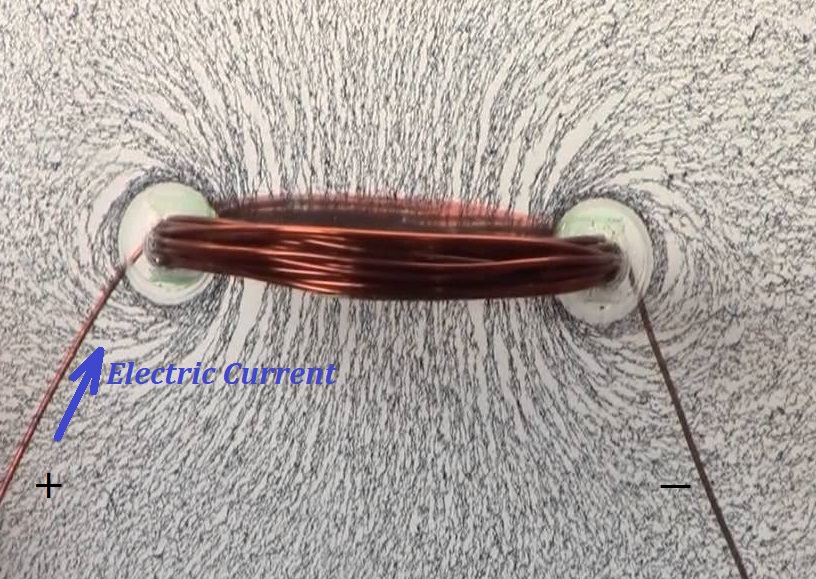
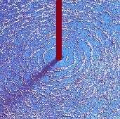
As we know from a previous lecture, the magnetic field force lines
around a long thin straight line wire with electric current running
through it are circular in planes perpendicular to a wire and centered
at the points of the wire.
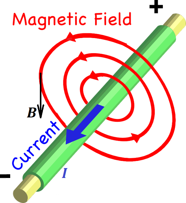
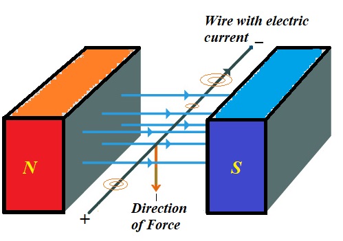
These lines are attributed a direction that can be determined using the rule of the right hand or Maxwell's corkscrew rule.
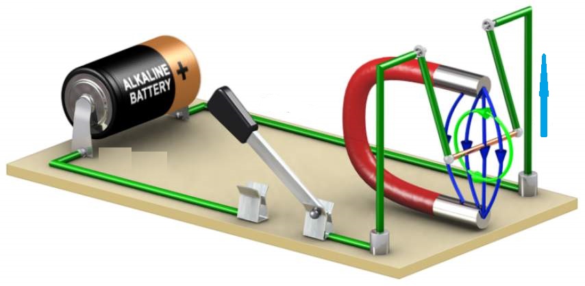
The rule of the right hand states that, if you wrap your right
hand around a wire such that your thumb points to a direction of an
electric current in the wire, which is, by definition, from positive to
negative, then your fingers will point to a direction of the magnetic
field lines. This direction is the direction of any tangential to a line
vector of force.
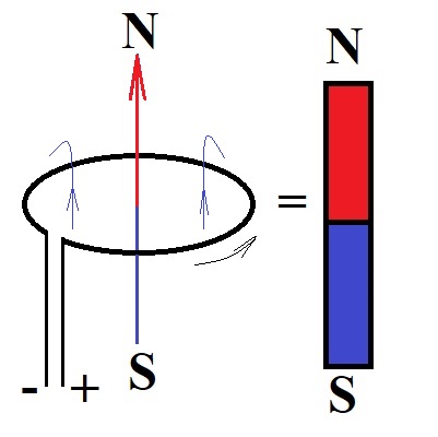
The corkscrew rule states that, if we imagine a corked bottle
along the wire such that the direction of an electric current enters the
bottle through a cork, to open the bottle we need to rotate the regular
cork opener in the direction of the magnetic lines around the wire.
The magnitude of the intensity of a magnetic field (a vector of force) depends on the electric current's amperage I and the distance R to the wire as follows
B = μ0I/(2π·R)
where μ0 is a constant called permeability of vacuum.
The direction of this force vector at any point of space around a wire
is always in the same plane as a circular magnetic line going through
the same point and is tangential to this magnetic line.
The direction of the vector corresponds to the direction of the magnetic line.
Problem 1A
Two ideally long and thin wires are positioned in space with Cartesian coordinates.
One goes through point A(0,0,a) on Z-axis (a > 0) parallel to X-axis and carries an electric current of amperage I in the positive direction of X-axis.
Another wire goes through point B(0,0,−a) on Z-axis parallel to Y-axis and carries an electric current of the same amperage I in the positive direction of Y-axis.
Determine the X-, Y- and Z-components and magnitude of the vector of magnetic field intensity at the origin of coordinates (0,0,0).
Solution
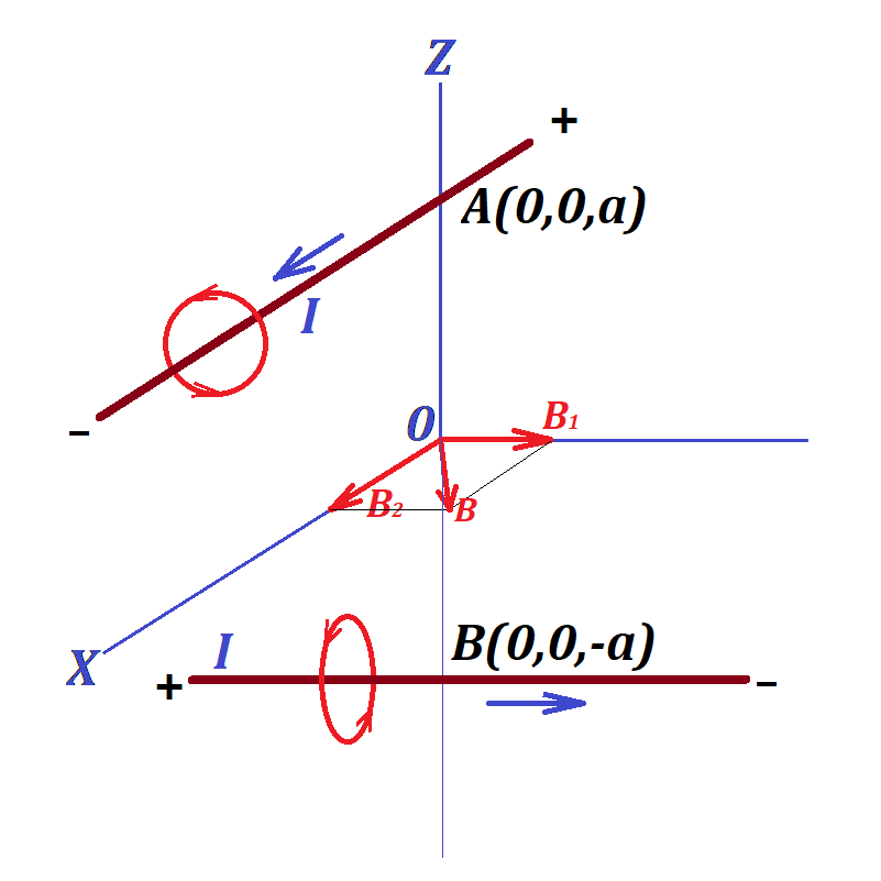
The magnetic field at point (0,0,0) is a combination of two fields - one with intensity vector B1, the source in the first wire that carries electric charge I parallel to X-axis, from which the origin of coordinates is at distance a, and another with intensity vector B2, the source in the second wire that carries electric current I parallel to Y-axis, from which the origin of coordinates is at distance a.
The resulting field intensity vector is a vector sum of vectors B1 and B2.
The first magnetic field has its force lines forming a cylindrical
surface with an axis being the first wire parallel to X-axis. At point (0,0,0) the direction of this magnetic field intensity vector is perpendicular to a radius from the first wire towards point (0,0,0), that is along the Y-axis towards its positive direction.
Considering the values of electric current I and the distance to the source (the first wire) equaled to a, the magnitude of this vector is
|B1| = μ0·I/(2π·a)
So, this vector in Cartesian coordinates is
{0; μ0·I/(2π·a); 0}
The second magnetic field has its force lines forming a cylindrical
surface with an axis being the second wire parallel to Y-axis. At point (0,0,0) the direction of this magnetic field intensity vector is perpendicular to a radius from the second wire towards point (0,0,0), that is along the X-axis towards its positive direction.
Considering the values of electric current I and the distance to the source (the second wire) equaled to a, the magnitude of this vector is
|B2| = μ0·I/(2π·a)
So, this vector in Cartesian coordinates is
{μ0·I/(2π·a); 0; 0}
Therefore, the combined vector of magnetic field intensity has its three coordinates
{μ0·I/(2π·a); μ0·I/(2π·a); 0}
The magnitude of this vector is
μ0·I·√2/(2π·a)
Problem 1B
Two ideally long and thin wires are positioned in space parallel to Z-axis.
One goes through point A(a,0,0) (a > 0) and carries an electric current of amperage I1 in the negative direction of the Z-axis.
Another wire goes through point B(0,b,0) (b > 0) and carries an electric current of amperage I2 in the positive direction of the Z-axis.
Determine the X-, Y- and Z-components and magnitude of the vector of magnetic field intensity at the origin of coordinates (0,0,0).
Solution
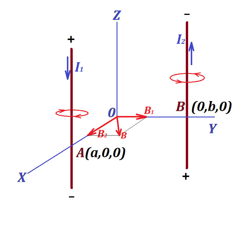
The magnetic field at point (0,0,0) is a combination of two fields - one with intensity vector B1, the source in the first wire that carries electric charge I1, from which the origin of coordinates is at distance a, and another with intensity vector B2, the source in the second wire that carries electric current I2, from which the origin of coordinates is at distance b.
The resulting field intensity vector is a vector sum of vectors B1 and B2.
The Z-coordinate of both vectors is zero.
The first magnetic field has its force lines forming a cylindrical surface with an axis being the first wire. At point (0,0,0) the direction of this magnetic field intensity vector is perpendicular to a radius from the first wire towards point (0,0,0), that is along the Y-axis towards its positive direction.
Considering the values of electric current I1 and the distance to the source (the first wire) equaled to a, the magnitude of this vector is
|B1| = μ0·I1/(2π·a)
So, this vector in Cartesian coordinates is
{0; μ0·I1/(2π·a); 0}
The second magnetic field has its force lines forming a cylindrical surface with an axis being the second wire. At point (0,0,0) the direction of this magnetic field intensity vector is perpendicular to a radius from the second wire towards point (0,0,0), that is along the X-axis towards its positive direction.
Considering the values of electric current I2 and the distance to the source (the second wire) equaled to b, the magnitude of this vector is
|B2| = μ0·I2/(2π·b)
So, this vector in Cartesian coordinates is
{μ0·I2/(2π·b); 0; 0}
Therefore, the combined vector of magnetic field intensity has its three coordinates
{μ0·I2/(2π·b); μ0·I1/(2π·a); 0}
The magnitude of this vector is
[μ0/(2π)]√(I1/a)²+(I2/b)²