Thursday, August 27, 2020

Three-phase AC: UNIZOR.COM - Physics4Teens - Electromagnetism - Alternat...


Notes to a video lecture on http://www.unizor.com


Three Phases AC


The Basic Principle

of 3-Phase AC Generation


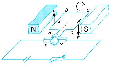
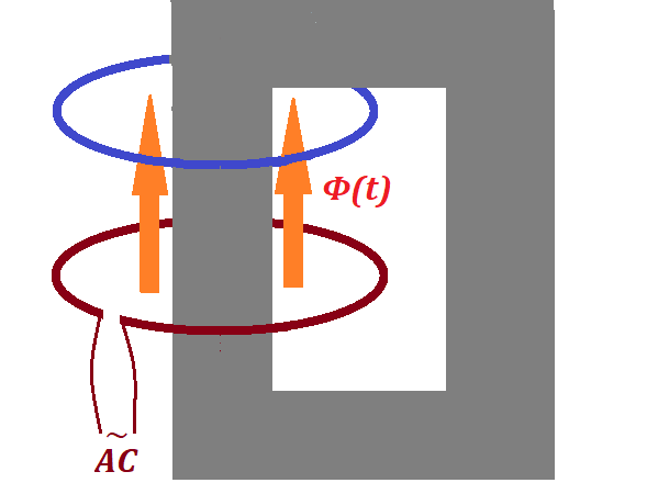
Recall the process of generating alternating current (AC) using a pair
of permanent magnets and a wire frame (a coil) rotating around the axis
perpendicular to magnetic field lines.

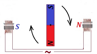
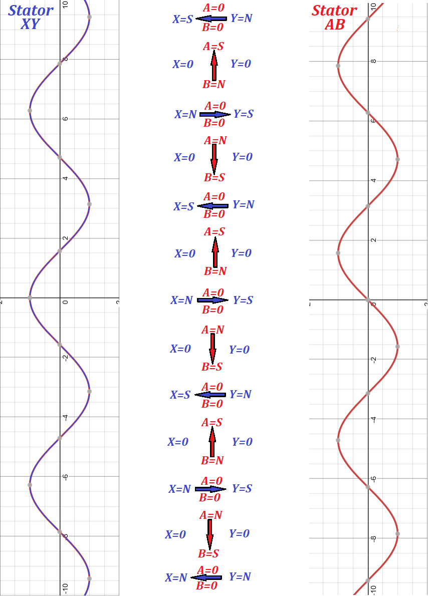
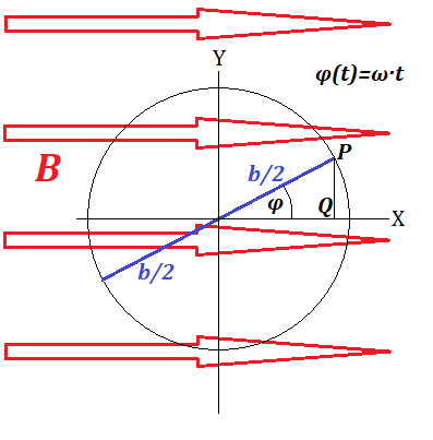
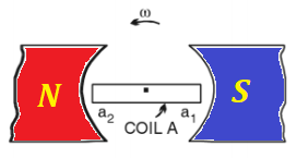
The pictures below represent the schematic design of such a system and a
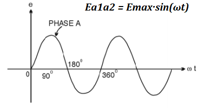
graph of an electromotive force (EMF) generated between the ends a1 and a2 of the wire frame

Ea1a2 = Emax·sin(ωt)

where

Emax is the maximum absolute value of EMF,

ω is the angular speed of rotation of the wire frame,

t is time.


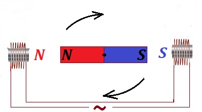
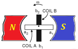
An obvious improvement to this design is to use the power of rotation
more efficiently by having two wire frames on the same axis positioned
perpendicularly to each other. In this case we can have two independent
sources of EMF with the only difference of one of them to be shifted in
time relatively to another by 1/2 of the time of rotation.

This shift is related to a simple fact that at the moment one wire
frame, aligned along the magnetic line, crosses these magnetic lines
with the highest rate, while another wire frame, that is perpendicular
to magnetic field lines, moves along these lines without actual
crossing. Then the roles are changed, as the coils rotate.

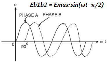
The EMF between the ends b1 and b2 of the second wire frame will then be

Eb1b2 = Emax·sin(ωt−π/2)


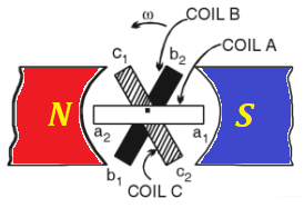
Why stop at two wire frames? Let's have three coils positioned at 120°
relative to each other. Now we will have three independent sources of
EMF shifted in time from each other by 1/3 of the time of rotation (phase
shift) - the time needed by one wire frame to take the position between
the magnet poles, previously taken by another wire frame.

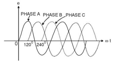
Three different EMF, therefore, will be equal to

Ea1a2 = Emax·sin(ωt)

Eb1b2 = Emax·sin(ωt−2π/3)

Ec1c2 = Emax·sin(ωt−4π/3) = Emax·sin(ωt+2π/3)


Practical Implementation


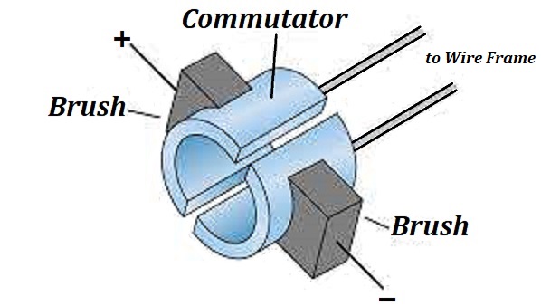
The design of a three phase generator, as depicted above, is just the
first try of an idea. If the magnet is fixed and three wire frames
(coils) are rotating between its poles, it presents a problem to connect
these coils to transmit the generated electricity to consumers, we need
sliding contacts, brushes and other impractical devices.


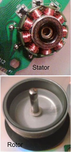
In real life generators the three coils make up a stator - a fixed part
of a generator, while the magnet is rotating inside a circle of coils by
external power (like steam, water, wind etc.), generating the
alternating current in the coils, which allows to make an electric
connection to coils fixed.


At the first glance, three coils have three pairs of connections with
sinusoidal EMF generated in each pair and, to transfer AC electricity
from all coils to consumers, we seem to need three pairs of wires, two
from each coil - six wires altogether. This, however, can be improved by
using the following technique.

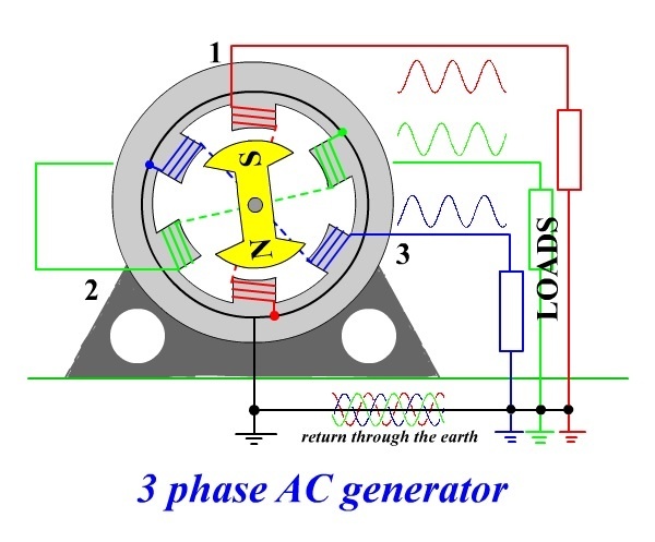
Let's connect ends a2, b2 and c2
of three coils together (see a picture below, it's a black wire at the
bottom connected to a black circle going around all coils) and see what
kind of resulting voltage will be observed on each end of the coils.
This is called a star connection of the generator's coils.


We know that the electric potential (EMF) on each of the above contacts
has a sinusoidal magnitude with a time shift by 1/3 of a period relative
to each other. When we connect these three contacts, the potential at
the joint will be

E0 = Emax·sin(ωt) + Emax·sin(ωt−2π/3) + Emax·sin(ωt+2π/3) = Emax·X

where

X = sin(ωt) + sin(ωt−2π/3) + sin(ωt+2π/3) =

= sin(ωt) + sin(ωt)·cos(2π/3) − cos(ωt)·sin(2π/3) + sin(ωt)·cos(2π/3) + cos(ωt)·sin(2π/3) =

= sin(ωt) + sin(ωt)·(−1/2) − cos(ωt)·(√3/2) + sin(ωt)·(−1/2) +
cos(ωt)·(√3/2) = 0


Therefore, E0 = 0

There will be no difference in electrical potential between the joint and the ground.


This fact enables to transmit all three phases of generated electricity along four wires - one from a1 (phase 1) contact, one from b1 (phase 2) contact, one from c1 (phase 3) contact and one neutral from a joint connection to a2, b2 and c2.

The neutral wire is usually grounded since its electric potential is equal to zero.


With this arrangement we still have an advantage of having three
independent phases of alternating current, but we need only four wires
to transmit it - three phase wires and one neutral.

Connecting any device to any phase and a neutral wires, we will get a closed circuit with AC running in it.


Energy Consideration


Obviously, putting two or three coils in a stator of a generator doubles
or triples the energy output carried by outgoing wires. The Law of
Energy Conservation must work, so where is the energy is coming from?


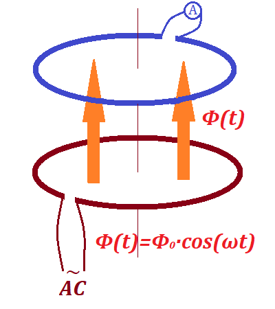
Recall the electromagnetic induction experiment described in the lecture
"Faraday's Law" in the "Electromagnetic Induction" chapter of this
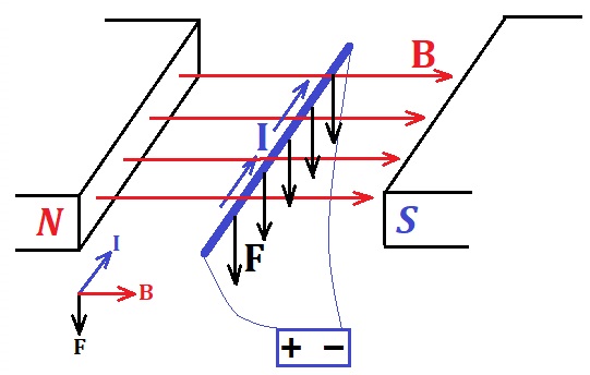
course with a wire moving in the uniform magnetic field.


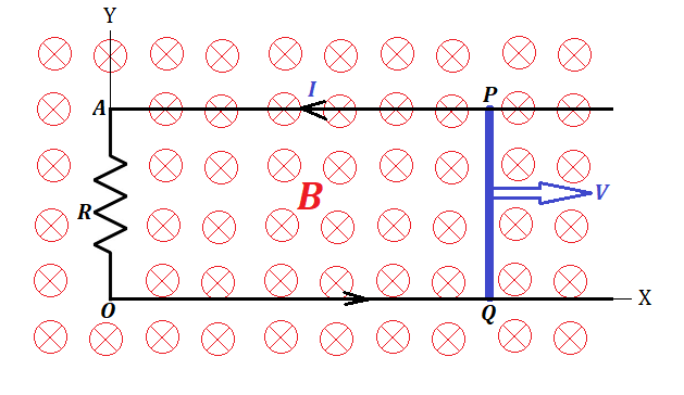
Since we physically move wire's electrons in one direction
perpendicularly to magnetic field lines, the Lorentz force pushes them
perpendicularly to both, the direction of the movement of a wire and the
direction of the magnetic field lines, that is, along the wire, thereby
creating an electric current between wire ends.


Now electrons are moving with a wire in one direction and along the wire in another.

The first movement maintains the electric current in the wire, but the
second, again, is a subject of the Lorentz force that pushes the
electrons perpendicularly to their direction, that is opposite to the
original direction of a wire movement.

This force resists the movement of a wire in its original direction. We
have to perform work against this force to move the wire.


Similar considerations are true in a case of a circular movement of a
wire frame in a magnetic field or, if wire coils are in a stator, the
force is needed to rotate the magnet in a rotor. That is, we have to
spend energy to generated the electricity, the rotor's rotation is
possible only if we apply the force against the Lorentz forces resisting
this rotation. The magnetic field generated by the electric current in a
wire coil of a stator resists the rotation of a magnet in a rotor.


If we have more than one coil in a stator, each one resists the rotation
of a rotor, so we have to spend proportionally more effort to rotate
the rotor.

The Law of Energy Conservation works. The more coils we have in a stator
- the more electricity is generated, but the more resistance to a
rotor's rotation needs to be overcome.


Three Phase AC Motor


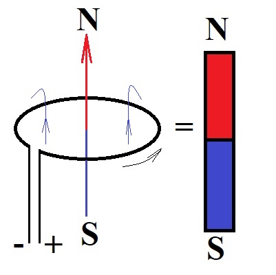
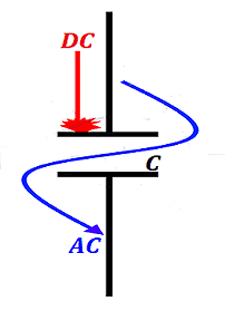
The lecture "AC Motors" of this chapter described the necessity of having a rotating magnetic field to make an AC motor.

To achieve such a rotating field we had to resort to artificially create
a second AC current with a phase shift by 90° using a capacitor or a
transformer.

Most of household AC motors (like in a fan) work on this principle, they need only two wires, which are, as we can say now, a phase wire and a neutral one.


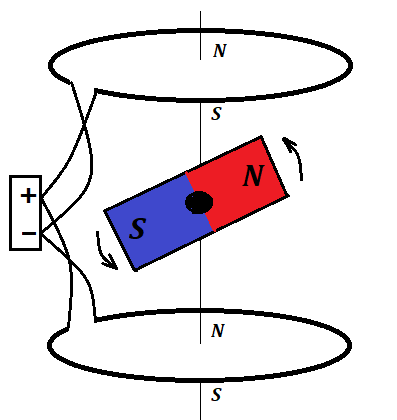
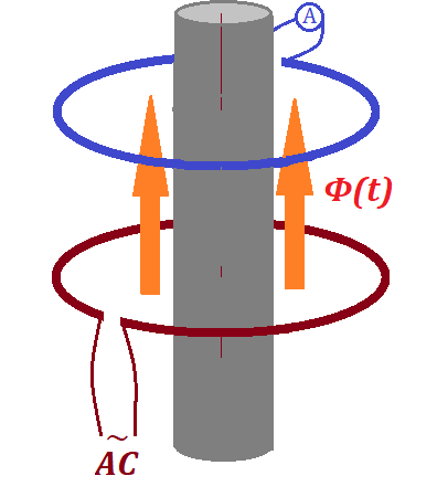
Powerful industrial level AC motors (like in a water pump that works in a
tall building to pump water to the roof tank) needs more power, and we
can use all three phases to create a rotating magnetic field.


So, all four wires coming from the AC generator, three phase wires and one neutral
one go into an AC motor, whose principal construction very much
resembles the one described in the previous lecture. The only difference
is, we already have three wires with AC phase shifted by 120°
relatively to each other. So, we have to position three wire coils in a
stator at 120° angles to each other, connect one end of each coil to a
corresponding phase wire and another end - to a common neutral
wire, and the rotating field is ready. Then it will work pretty much as
it was described in the "AC Motors" lecture, but smoother because three
phases make a smoother rotation of a magnetic field than two phases.


At the end I would like to say again, that it was Nicola Tesla's genius
that created all the basic principles, based on which all the current AC
motors are working now. His contributions to our industrial development
are grossly underappreciated. Calling an electric car model "Tesla" is a
late but well deserved tribute to his creativity.

Sunday, August 23, 2020

AC MotorsUNIZOR.COM - Physics4Teens - Electromagnetism - Alternating Cur...


Notes to a video lecture on http://www.unizor.com


Alternating Current Motors


Alternating current (AC) motors are used where the sources of electricity produce alternating current - in our homes, at industrial facilities etc.

For example, AC motors work in refrigerators, water pumps, air conditioners, large fans and many other devices.


The idea of AC motors belongs to Nicola Tesla, who invented it at the end of 19th century.

And it was a brilliant idea!


Before talking about AC motors, let's recall how DC motors are working.
Their basic design was presented in a lecture Physics 4 Teens -
Electromagnetism - Magnetism of Electric Current - DC Motors.


The important feature of DC motor, which was the starting idea behind
its design, was the rotational momentum exerted by a magnetic field of a
permanent magnet onto a wire frame with the direct electric current
going through it due to Lorentz force. Without a commutator or
any electronic switches the rotating frame would rotate until its plane
will reach a perpendicular position relative to magnetic lines, which
will be its equilibrium position.


Let's start with this idea of an AC motor and try to make it work.


Firstly, as in the case of DC motors, let's replace the permanent magnet
in a stator with two coils around an iron cores - electromagnets that
create magnetic field. Notice, however, that the current in these
electromagnets is alternating, which means that the magnetic field
between these electromagnets is alternating as well in magnitude and
direction.


Secondly, we will place a permanent magnet on an axis, so it freely rotates between the poles of the electromagnets


What will happen if we switch on the alternating current in the electromagnets?

Well, nothing noticeable. The problem is, the polarity of electromagnets
will start switching with frequency of the AC - 50 or 60 oscillations
per second in usual commercial wiring, and a permanent magnet in-between
will be forced in two opposite directions with the same frequency and
it will not start rotating.


But let's manually start rotating the magnet in any direction strong
enough to force it to rotate with significant angular speed.

At different positions the variable external magnetic field of
electromagnetic stator interferes with rotating permanent magnet rotor,
sometimes slowing it, sometimes speeding its rotation.

In a short while the rotation of the permanent magnet rotor will
synchronize with variable external field of electromagnetic stator and
rotation will be maintained with the same angular speed as the frequency
of AC in the coils of electromagnets.


Let's analyze this rotation in steps after the synchronization is achieved.

Let a pole facing the rotor of one electromagnet be X and an opposite pole of another electromagnet be Y.

As AC changes its direction and magnitude, pole X is gradually changing
from North (X=N) to zero (X=0), to South (X=S), again to zero (X=0),
again to North (X=N) etc.

At the same time pole Y of an opposite electromagnet is gradually
changing from South (Y=S) to zero (Y=0), to North (Y=N), again to zero
(Y=0), again to South (X=N) etc.


Synchronously rotating permanent magnet of a rotor should with its North
pole approach X=S and, simultaneously, with its South pole approach
Y=N.


As a rotor approaches with its poles the poles of a stator, X and Y
should gradually weaken and, when the permanent magnet is fully aligned
along XY line, the magnitudes of the magnetic fields of electromagnets
should diminish to zero (X=0, Y=0).


Permanent magnet rotor will pass this point by inertia and the polarity of the electromagnets switches, so now X=N and Y=S.


That causes rotation to continue until the permanent magnet of a rotor again takes a position along XY line.

By that time the electromagnets will be at X=0 and Y=0, rotor will
continue rotation by inertia, then AC switches the polarity of
electromagnets again and rotation continues in a similar manner
indefinitely.


Our first version of an AC motor is functional, but it has two obvious disadvantages.

One disadvantage is the usage of permanent magnet, they are very
expensive. We could not avoid it in a DC motor, but in an AC case we
might think that variable magnetic field might help to use the induction
effect to avoid it.

Another disadvantage is that switching the AC on does not really start
the rotation, we manually started it, and only then, if we gave a strong
push, it started to rotate and maintained this rotation.


Let's use a wire loop instead of a permanent magnet rotor. But, to act
as a permanent magnet, it needs an electric current running through the
wire, and we don't want any extra sources of electricity to connect to
it, it's complicated, needs a commutator, like in the original DC
motors.

Instead, we will count on the induction effect created by an alternating
current in a stator, which creates an alternating magnetic field,
which, in turn, induces the electric current in the wire loop of a
rotor.


The induced electric current in a wire loop of our rotor appears when a
wire crosses the magnetic field lines. Magnetic field produced by a
stator is directed always along a center line XY and is changing in
magnitude from a maximum in one direction (from X to Y) to zero, to a
maximum in another direction (from Y to X), again to zero etc.


The problem is, if the rotor is standing still, its wire does not cross
magnetic field lines. Therefore, no electric current will be produced in
it, and there will be no rotation. Rotor needs an initial push
sufficient to synchronize its rotation with the frequency of alternating
magnetic field to continue the rotation. Our second disadvantage is
still unresolved.


Let's imagine that, besides two main electromagnets with poles X and Y,
we have another pair of auxiliary electromagnets in a stator, that are
positioned perpendicularly to line XY. Let their poles be A and B and
(very important!) the current in them, also sinusoidal, is shifted in
time relatively to a current in main electromagnets by 90°.

So, when the magnetic field in one direction is maximum along line XY,
it's zero along line AB; then it gradually decreases along XY and
increases along AB until it's zero along XY and maximum along AB. This
cycle repeats itself indefinitely.


Graphically, it can be represented as follows.


Graphs on the left and on the right of a picture represent the electric
current in each pair of electromagnets - XY and AB. Notice, they are
shifted by π/2=90°. The middle part of a picture represents the
direction of the magnetic field created by both pairs of electromagnets
of a stator.

As the time goes, the magnetic field direction is rotating. The rotating
magnetic field around a closed wire loop of a rotor causes the rotor's
wire to cross the magnetic field lines of a stator, which, in turn,
causes induction of electric current in a rotor's closed wire loop,
which will act now as a permanent magnet, which is supposed to follow
the rotation of the magnetic field around it.

This causes the rotation of the rotor. The rotor's actual physical
rotation will follow the stator's magnetic field rotation, created
without any physical movement.


The rotor cannot go after the stator's magnetic field rotation exactly
synchronously because then there will be no crossing of magnetic field
lines. So, the rotor, after it reached the same speed as the stator's
magnetic field rotation, will lose its rotational momentum and slow
down. Then the rotor's wire, rotating slower than the magnetic field
around it, will cross the magnetic field lines, there will be induction
current in it, it's magnetic properties will be restored and it will try
to catch up with the stator's magnetic field rotation. This process
will continue as long as AC is supplied.


An obvious improvement is to use multiple wire loops as a rotor with
common axis of rotation. That will cause more uniform rotation.


What's remaining in our project of designing the AC motor is to create
another alternating current for the second pair of electromagnets in a
stator with a time delay of π/2=90° relatively to the main AC.

This problem is resolved and described in the previous lecture about AC
capacitors. If we introduce another circuit fed from the same AC source,
but with a capacitor in it, this circuit will have the alternating
current shifted in time exactly as we want. This current will go through
the second pair of electromagnets and both pairs will create a
revolving magnetic field.


The interaction between magnetic fields of a stator and a rotor is quite
complex, when the rotor rotates. The magnetic flux going through a
rotor wire loop depends on a variable magnetic field of a stator and
variable area of a rotor wire loop in a direction of a magnetic field
lines of a stator. The exact calculations of this process are beyond the
scope of this course.

The main idea, however, is clear - to create an AC motor we have to create a revolving magnetic field - the great idea of Nicola Tesla. That can be accomplished by using known methods described above.

Wednesday, August 19, 2020

DC Motors: UNIZOR.COM - Physics4Teens - Electromagnetism - Magnetism of ...


Notes to a video lecture on http://www.unizor.com


Direct Current Motors


Direct current (DC) motors are used where the sources of electricity produce direct current, like batteries.

For example, DC motors work in car engine starter, computers, toys, drones and many other devices.


We will concentrate on principles of their work without going into many
details. Basically, we will describe these motors as they were first
thought of by their inventors. Obviously, initial ideas were further
improved by many people and improvements are still introduced after more
than 200 years after their invention, but the basic ideas are still
there.


Let's start with the idea of the DC motor.

The beginning of a development of a DC motor is associated with a simple
experiment we described before - the one that demonstrated the Lorentz
force on a current in a magnetic field.

If the direction of a current I is perpendicular to a direction of magnetic field lines B,
the magnetic field "pushes" the conductor that carries this current in a
direction perpendicular to both magnetic field lines and a current by
force F.


The first modification of this experiment was to use a rectangular wire
frame instead of a straight line conductor and let it spin around an
axis. The force exerted by a magnetic field will act on both sides of a
wire frame that are perpendicular to magnetic lines in opposite
directions, creating a rotational momentum, so the frame with rotate.


The force F of a magnetic field "pushes" segment AB up and segment CD, where the electric current goes in an opposite to segment AB direction, is "pushed" down by this force. This creates a rotational momentum.


The problem is, the rotation will stop when the wire frame plane will be
perpendicular to a direction of a magnetic field, because the forces
exerted by a magnetic field on both sides of a wire frame AB and CD
will no longer create a rotating momentum, they will act against each
other within the wire frame plane and after a short oscillation caused
by a rotational inertia the rotation stops.


On the picture above, when the plane of a wire loop reaches the position perpendicular to the magnetic field force, the segment AB will be on the top and the magnetic field force F will "push" this segment up. Segment CD will be on the bottom and the magnetic field force F
will "push" this segment down. Both forces are acting within the same
plane with the axis of rotation and nullify each other. No rotational
momentum is created.


Our next improvement is related to overcoming this problem.

What happens if exactly at the moment when our wire frame plane is
perpendicular to magnetic field, when the forces exerted by a magnetic
field no longer create a rotational moment, we switch off the electric
current in a wire and a very short moment later we switch it on, but in
the opposite direction of the electric current?

First of all, the rotation will continue by inertia during the time
electricity is off. Then, we turn the electric current on but in
opposite direction. That means, the direction of the magnetic field
force will change to an opposite. Segment AB will be "pushed" down, segment CD
will be "pushed" up. Since the wire frame has passed the point of
perpendicularity to magnetic field by rotational inertia during electric
current off time, the newly formed magnetic field forces will create a
rotational moment and the direction of rotation will be the same as
before.


Our frame will continue the rotation in the same direction until segment AB will be on the bottom and segment CD - on the top.

At that moment we will do the same switching off the electric current to
let our frame pass the perpendicular position towards the magnetic
field force, and a very short moment later we switch electric current on
in an opposite direction. Now segment AB will be "pushed" up again, segment CD will be "pushed" down, which will allow to complete the cycle of rotation and the rotation will continue in the same direction.


All we need is to explain how to switch the direction of an electric current.

Here is a drawing of this simple device called commutator.


Direct current comes through brushes to a commutator and to a revolving
frame connected to it. As this construction revolves, the brushes lose
the contact with a commutator for a very short period, then again touch
the commutator, but with opposite poles.

That's how we change the direction of the current that forces the frame to constantly rotate in the same direction.


The inner rotating part of this type of a DC motor is called rotor, the outer stationary part with a magnet is called stator.

The detail implementation of this design of a DC motor is outside the scope of this course. Our purpose is to convey the idea.


The weak part of a DC motor design with brushes is that these brushes
wear out with time and are the source of sparks, which might be
prohibitive in some environments. Plus, they are noisy.

With development of electronics inventors came up with a better design
that does not involve brushes at all, rotation is accomplished without
any mechanical switches.


First step on the design of this brushless DC motor is to realize that
we have to invert the functionality of permanent magnet and a wire
frame. The need for a commutator with mechanical brushes was related to the fact that electric circuit was rotating.

Let's invert roles and put two parallel wire frames on opposite ends of a circle as a stator and a permanent magnet on an axis in the middle as a rotor.

Recall that a wire loop with direct current running through it acts like a magnet


Putting two such loops on opposite ends of a stator creates a magnetic
field and a freely rotating permanent magnet in between will have to
turn to align itself with the field of these two wire loops


If at the moment our permanent magnet aligns with magnetic field of both
wire loops we change the direction of electric current in the loops to
an opposite, thus changing the polarity of the magnetic field they
generate, the permanent magnet in between will have to continue the
rotation until it will align again. Repeating this cycle creates the
rotation of a permanent magnet.


This rotation will not be smooth. The force of magnetic field attraction
will create a stronger moment of rotation when the direction of the
permanent magnet is perpendicular to a direction of the magnetic field
of the loops. This can be improved by certain additional details
described below.


The changing of the direction of the current in the wire loops now is
much easier than in the previous design because the wires are not
moving. Simple electronic switch working off some kind of a marker on a
rotating permanent magnet can signal its position and trigger the switch
of direction of the current.


Basically, the idea is finished here. But some very important improvements should be mentioned.


1. Instead of a single wire loop we can use a copper coil around an iron
core to make the magnetic field of this electromagnet stronger.


2. Instead of a pair of such electromagnets with switching the direction
after the permanent magnet in the middle turns by 180°, we can use two
pairs and properly engage another pair after 90° turn, switching off the
previous pair, thus creating a rotating magnetic field that results in a
smoother movement of a permanent magnet rotor. Even better, we can use
three pairs of electromagnets and engage another pair after each 60°,
switching off the previous two pairs. This will allow even smoother
rotation. In some DC motors they use even six pairs of electromagnets,
which results in a very uniform rotation with practically constant
angular speed.

The electronic switches that engage and disengage the coils can be designed for any type of coil arrangement.


3. Instead of a bar permanent magnet inside the circle of electromagnets
we can use a ring permanent magnet outside it. It creates a better
response to a revolving magnetic field of a stator, the rotation will be
smoother because of inertia of a rotating ring.


With all the above improvements the DC motor used in hard disk of computers and other devices looks like the one below


This DC motor has 9 electromagnets sequentially engaged after each 40° turn of a rotor.

Rotor is a ring-shaped permanent magnet that rotates around the electromagnets.

A marker on the rotor sends a signal to an electronic switch to indicate
the position of a rotor, which is used by electronics on the attached
board to properly engage the electromagnets of a stator.


The most important detail of this design of a DC motor is the rotating
magnetic field achieved through purely electronic means without any
moving parts. This results in a smooth rotation of a rotor made of a
ring permanent magnet around a stator.

Saturday, August 15, 2020

AC Capacitors: UNIZOR.COM - Physics4Teens - Electromagnetism - AC Induction


Notes to a video lecture on http://www.unizor.com


Alternating Current and Capacitors


Let's start with a clear illustration of what we will discuss in this lecture.


The main idea is that alternating current (AC) goes through a capacitor, while direct current (DC) does not.


To explain this fact, consider how electricity is produced in both cases DC and AC.


For DC case we will use a battery that uses some chemical reaction to
separate some outer layer ("free") electrons from their atoms and moves
them toward a battery's negative pole, where excess of electrons will be
present, leaving deficiency of electrons on the positive pole.


If we connect the poles of this battery to two plates of a capacitor,
the excess of electrons from the negative pole of a battery will travel
to one plate, while the deficiency of electrons will be on the other
plates. It will continue until we reach a saturation of electrons on one
plate and their absence on another. The electromotive power of the
battery could not push electrons anymore to one plate, because their
repulsive force will be too strong. And that's it. Electrons will not
jump from one plate of a capacitor to another (unless the EMF of a
battery is so strong that it breaks the isolation between the plates of a
capacitor, which defeats the purpose), the circuit is not closed, the
current will not go through.


In AC case the generated electromotive force (EMF) is variable in magnitude and direction.


It starts with separating "free" electrons from their atoms, gradually
increasing the concentration of electrons on one pole and on the
capacitor's plate connected to it.

At the same time deficiency of electrons is observed on the other pole and a capacitor's plate connected to it.


That lasts for some short period of time (half a period), when the
generated EMF gets weaker and goes down to zero. This causes the excess
electrons from one capacitor plate to go back to a generator and
compensate the deficiency of electrons on the other plate. This ends
half a period of EMF oscillation.


On the next half a period the EMF changes the sign, electrons will be
accumulated on the plate, where previously we observed their deficiency.
On the plate where we had excess of electrons during the previous half a
period we will have their deficiency.


So, during the full cycle of two half-periods electrons move to one
plate of a capacitor, then back to a generator and to another plate of a
capacitor. Then the cycle repeats itself, electrons move within a
circuit with a capacitor back and forth, thus facilitating the
alternating current in this circuit.


Let's compare the alternating current in a case of a closed circuit without a capacitor with a circuit that has a capacitor.

We start in both cases with a device that generates alternating sinusoidal EMF

U(t) = Umax·sin(ωt)

where

U(t) is the generated EMF as a function of time t,

Umax is the peak value of EMF,

ω is the angular speed of rotation of a device generating the alternating EMF.


In a closed circuit with an alternating EMF and no capacitors, according to the Ohm's Law, the electric current I(t), as a function of time t, will be proportional to an EMF and will alternate synchronously with it

I(t) = Imax·sin(ωt)

where

Imax is the peak value of electric current in a circuit.


In case of a capacitor being a part of a circuit the situation is more complex.

As we know, the amount of electricity Q(t) accumulated in the capacitor is proportional to voltage U(t) applied to its plates, and capacity of a capacitor C
(see lecture "Electric Fields" - "Capacitors" in this course) is the
constant proportionality factor that depends on a type of a capacitor

C = Q(t)/U(t)


Therefore,

Q(t) = C·U(t) = C·Umax·sin(ωt)

Knowing the amount of electricity Q(t) accumulated in a capacitor as a function of time t, we can determine the electric current I(t) in a circuit, which is a rate of change (that is, derivative by time) of the amount of electricity

I(t) = dQ(t)/dt =

= C·Umax·ω·cos(ωt) =

= Imax·cos(ωt) =

= Imax·sin(ωt+π/2)


where

Imax = C·Umax·ω


Incidentally, expression which is called reactance, plays for a capacitor similar role to that of a resistance because, using this reactance, the formula for a peak value of the electric current in a circuit with a capacitor resembles the Ohm's Law

Imax = Umax/XC


What's most important in the formula I(t)=Imax·sin(ωt+π/2)
and the most important property of a capacitor in an AC circuit is
that, while an EMF in a circuit oscillates with angular speed ω, the electric current oscillates with the same angular speed ω as EMF, but its period is shifted in time by π/2 relative to EMF.


This is a very important capacitor's property used in AC motors, which will be a subject of the next lecture.

XC = 1/(ω·C),

Thursday, August 13, 2020

AC Induction: UNIZOR.COM - Physics4Teens - Electromagnetism


Notes to a video lecture on http://www.unizor.com


Alternating Current Induction


The Faraday's Law of electromagnetic induction states that a variable magnetic flux Φ(t) going through a wire loop generates in this wire loop an electromotive force EMF=U(t) equal in magnitude to a rate of change of the magnetic flux:

U(t) = −dΦ(t)/dt

where the meaning of the minus sign was explained in the lecture about self-induction previously in this course.


There are different ways to generate a variable magnetic flux. For
example, we can physically move a permanent magnet through or around a
wire loop, which will generate EMF in the wire.

But, having alternating current (AC) at our disposal and knowing
that any electric current creates a magnetic field around it, we can
create a variable magnetic field just by running AC through a wire.


Let's start from a simple experiment just to demonstrate the principle of AC induction.


Here the bottom wire loop (we will call it primary) is connected to a source of an alternating current, while the top wire loop (secondary)
has no source of electricity, but is connected to a device to measure
the effective electric current in it - an AC ammeter (or amp-meter, or
ampermeter).


Since the AC in the primary loop is variable (more precisely, sinusoidal), the intensity of the magnetic field generated by it is also variable.


Therefore, the magnetic flux going through the secondary loop is
variable (also sinusoidal) with the generated EMF (first derivative of
magnetic flux) not equal to zero and also sinusoidal since the
derivative of sin(x) is cos(x) and derivative of cos(x) is −sin(x), as we know.


Variable (sinusoidal) EMF in the secondary loop causes the variable
(sinusoidal) electric current in it, which we can observe on the AC
ammeter.

We have just demonstrated the principle of AC induction -
transformation of the alternating electric current from one circuit
(primary loop) to another (secondary loop) without physical connection
between them.


Let's switch to more practical aspects of AC induction.


Recall from the earlier presented lecture "Magnetism of Electric Current in a Loop" that the intensity B of a magnetic field at the center of a wire loop in a vacuum equals to

B = μ0·I/(2R)

where

μ0 is the permeability of free space,

I is the electric current going through a wire loop (maybe variable as in the case of AC),

R is the radius of a wire loop.


If, instead of a vacuum, we have some other material inside a loop, the
intensity of a magnetic field will be different. The formula will be
almost the same, just the permeability of free space μ0 should be replaced with permeability of the corresponding material μ.


Experimentally obtained data tell us that one of the greatest permeability
is that of so-called ferromagnetic materials - those that contain iron.
Actually, pure iron has the permeability of about 200,000 greater than
vacuum. So, if we have a ferromagnetic material inside the primary wire
loop in our experiment, the magnetic energy will have a choice - to go
through highly resistant space around this ferromagnetic material or to
go through it with much less resistance.


The general principle of field propagation is that the most energy goes
through least resistance. So, we can expect that ferromagnetic material
inside the wire loop will concentrate the magnetic field generated by a
primary wire loop and much less of the field energy will be dissipated
around it.


Our first improvement to the experiment above is to use a cylinder made of ferromagnetic material going through both our loops.


Ferromagnetic material has temporary magnetic properties and quickly
reacts to external magnetic field by rearranging the orientation of its
atoms. The variable magnetic field created by AC inside the primary loop
will force the atoms inside this cylinder to react by orienting along
the vector of intensity of the magnetic field, thus increasing this
intensity.

So, the purpose of this ferromagnetic cylinder going through both loops
is to increase the intensity of the magnetic field going through the
secondary wire loop without spending any more energy. The ferromagnetic
cylinder just concentrates and directs more of the energy of the
magnetic field to go through the secondary wire loop and less will be
dissipated outside the secondary loop.


Still, the energy of magnetic field generated by the primary wire loop
and directed through the ferromagnetic cylinder through both loops will
be dissipated from the ends of this cylinder.

To make our induction even more efficient, we can close the magnetic
field on the ends of a ferromagnetic cylinder as on this picture:


Now the magnetic field is not dissipated outside the ferromagnetic
material, and almost all energy generated by the primary wire loop with
AC running through it is used to create the magnetic flux inside the
secondary wire loop.


Our next practical improvement is related to the fact that the vector of
intensity of a magnetic field is an additive function. That is, the
intensity of a combined magnetic field of two or more sources equals to a
vector sum of intensities of all component fields.


We can use multiple loops in the primary coil, which is a source of
magnetic field, instead of a single primary wire loop in our experiment.

Let's wind NP primary loops of wire in a coil around
our ferromagnetic core. Connected to the same source of AC and having
the same sinusoidal current going through them, each loop will create a
magnetic field and all these NP fields will have to be added together to get the resulting magnetic field intensity.


So, the generated magnetic flux of such a coil will be NP times greater than the one by a single loop. Its inductive effect on the secondary wire loop will be NP times stronger.


As the next practical improvement of our experiment, let's use a coil of NS wire turns instead of a single secondary loop.

Each turn of this secondary winding will have the same magnetic flux
flowing through it and will induce an electromotive force (EMF)
proportional to a rate of change of magnetic flux. All these EMF in each
turn of a secondary wire are sequential to each other and should be
added together to get the resulting EMF in the secondary circuit.

So, the EMF induced in a secondary coil of NS wire turns will be NS stronger then the EMF induced in a single secondary loop.


So, changing the number of turns in the primary wire coil NP,
we proportionally change the variable magnetic flux, which, in turn,
proportionally change the induced EMF in the secondary coil.

Analogously, changing the number of turns in the secondary wire coil NS, we proportionally change the induced EMF in this wire coil.

These two facts lead us to use the device we have constructed to
transform the EMF of alternating current for whatever purpose we need.


Indeed, if NP=NS and our device is
ideal in a sense that the energy does not dissipate and the coils are
not heated up because of internal resistance, the same magnetic flux
goes through the same coils, which means the EMF in both primary and
secondary coils is the same.


If we want to induce the secondary EMF twice as stronger as the primary
one, we can double the number of turns in the secondary coil.

If we want to induce the secondary EMF twice as weaker as the primary
one, we can reduce the number of turns in the secondary coil by half.


This can be expressed as

UP(t)/US(t) = NP/NS

where

UP(t) is the EMF in the primary coil,

US(t) is the EMF in the secondary coil,

NP is the number of wire turns in the primary coil,

NS is the number of wire turns in the secondary coil.


But changing the EMF has its consequences.

The Conservation of Energy Law is still supposed to be held. The power
produced by AC in the primary coil in an ideal transformer is completely
transferred to the secondary coil, which means

P(t) = UP(t)·IP(t) = US(t)·IS(t)

where

P(t) is the power produced by primary and transferred to secondary coil, variable for AC,

UP(t) is the EMF in the primary coil,

IP(t) is the electric current in the primary coil,

US(t) is the EMF in the secondary coil,

IS(t) is the electric current in the secondary coil.


From the equation above follows that increasing the EMF in the secondary
coil causes proportional decreasing in the electric current in it and
vice versa:

UP(t)/US(t) = IS(t)/IP(t)


The formulas above are the basic principle of working of transformers -
devices used to increase the AC voltage, while proportionally decrease
the electric current and, therefore, decrease losses related to
transmission of electricity along long wires and also used to decrease
this voltage, while proportionally increase the electric current at the
location of homes and electric devices that need the lower voltage in
the outlets with higher amperage.

Friday, August 7, 2020

AC - Effective Voltage: UNIZOR.COM - Physics4Teens - Electromagnetism


Notes to a video lecture on http://www.unizor.com


Effective Voltage
and Current (RMS)


We all know the voltage in our outlets at home. In some countries it's
220V, in others 110V or some other. But we also know that electric
current distributed to consumers from power plants is alternating (AC).

The actual value of voltage and amperage are sinusoidal, changing with time as:

U(t) = Umax·sin(ωt)

I(t) = U(t)/R = Imax·sin(ωt)

where

ω is some parameter related to the generation of electricity at the power plant,

t is time,

Umax is the voltage amplitude,

Imax = Umax/R is the amperage amplitude,

R is resistance of the circuit where alternating current is running through.


If voltage is variable, what does it mean that in the outlet it is, for example, 220V?


The answer to this question is in comparing energy the electric current is carrying in case of a variable voltage with energy of a direct current.


The AC voltage is sinusoidal, so we can calculate the energy it carries through a circuit during the time of its period T=2π/ω and calculate the corresponding DC voltage that carries the same amount of energy during the same time through the same circuit.

That corresponding value of the DC voltage is, by definition, the effective voltage in the AC circuit, which is usually called just voltage for alternating current.


First, let's evaluate how much energy the AC with voltage U(t)=Umax·sin(ωt) carries through some circuit of resistance R during the time of its period T=2π/ω.


Consider an infinitesimal time interval from t to t+dt.
During this interval we can consider the voltage and amperage to be
constant and, therefore, use the expression of the energy flowing
through a circuit of resistance R for direct current:

dW(t) = U(t)·I(t)·dt = U²(t)·dt/R

(see "Electric Heat" topic of this course and "Ohm's Law" for direct current)


To calculate the energy going through a circuit during any period T=2π/ω, we have to integrate this expression for dW on an interval from 0 to T.

W[0,T] = [0,T]dW(t) =

= [0,T]U²(t)·dt/R =

= [0,T]max·sin²(ωt)·dt/R =

= (max/R[0,T]sin²(ωt)·dt


To simplify the integration we will use the known trigonometric identity

cos(2x) = cos²(x) − sin²(x) = 1 − 2sin²(x)

from which follows

sin²(x) = [1 − cos(2x)] /2


Next we will do the substitution

x = ω·t

t = x/ω

dt = dx/ω

t ∈ [0,T] x ∈ [0,ωT]=[0,2π]


The integral above, expressed in terms of x, is

[0,2π]sin²(x)·dx/ω =

=
[0,2π][1−cos(2x)]·dx/(2ω) =

=
[2π−[0,2π]cos(2x)·dx]/(2ω) =

= π/ω


Therefore,

W[0,T] = π·U²max/(ω·R)


At the same time we have defined the effective voltage as the one that delivers the same amount of energy as W[0,T] to the same circuit of resistance R during the same time T=2π/ω if the current is constant and direct.

That is

eff·2π/(R·ω) = W[0,T] = π·U²max/(ω·R)


Cancelling and simplifying the above equality, we conclude

2·U²eff = U²max

or

2·Ueff = Umax

For effective voltage 110V the peak voltage (amplitude) is 156V,

for effective voltage 120V the peak voltage (amplitude) is 170V,

for effective voltage 220V the peak voltage (amplitude) is 311V.

Tuesday, August 4, 2020

Properties of Alternating Current: UNIZOR.COM - Physics4Teens - Electrom...


Notes to a video lecture on http://www.unizor.com


Properties of

Alternating Current (AC)


Let's talk about practical aspects of electricity. We use it to light up
our homes, to move the motors that pump the water, to ignite the car
engine etc.

These are practical issues that must be resolved in the most efficient way.

A short statement about alternating electric current is that it allows to do things easier and more efficient than direct electric current.


The primary reason for using alternating electric current that allows to
perform all these functions more efficiently than using direct electric
current is that alternating electric current creates alternating magnetic field, that, in turn, can generate alternating electric current in another circuit through a mechanism of induction,
and at many points on the way of these transformations we can use some
device to extract some useful functionality, like rotate the motor.


Let's start from the beginning.

In order to use electricity, we have to generate it. In most cases we
convert mechanical movement into electricity at power plants. There are
other ways, like chemical reaction in the battery or solar panels, but
they produce limited amount of electricity currently used.


The most common way to transform mechanical motion into electricity is through induction. Recall, when we rotate a wire frame in the uniform magnetic field, the electric current is induced in the wire frame.


This process of generating electric current by transforming mechanical energy into electricity using the induction is at the heart of all power plants.

The simplest mechanical motion that can be used on industrial scale is
rotation. So, some mechanical source of energy can rotate the wire frame
in a permanent magnetic field, which generates the electric current,
that we can distribute through different circuits to different devices.


As we know, induced electromotive force (EMF) in a wire frame, rotating in a magnetic field, depends on the rate of change of magnetic flux through this frame. In a simple case of a uniform magnetic field of intensity B and a wire frame rotating with constant angular speed ω around an axis perpendicular to the direction of magnetic field lines the magnetic flux
going through a frame is changing with time, depending on the angle of
rotation of a wire frame and the direction of the vector of magnetic
field intensity.


The picture below represents the top view of a flat rectangular wire frame of dimensions a by b at some moment of time t, when the frame deviated by angle φ from its original position, which was parallel to the magnetic field lines.


As was calculated in a lecture about a rotation of a wire frame, the magnetic flux going through a frame is

Φ(t) = B·S·sin(ωt)

where S=a·b is the area of a wire frame.


The induced EMF U(t) in a wire frame equals to the rate of change of this flux:

U(t) = −dΦ(t)/dt = −B·S·ω·cos(ωt)

What's most important for us in this formula is that it shows the change of a magnitude and a direction of the induced EMF.

The dependence of U(t) on cos(ωt) shows that
the induced electric current in the wire loop and, consequently, in all
devices that receive this current from this wire loop and have combined
resistance R is changing from some maximum value Imax=B·S·ω/R down to 0, then it changes the direction to an opposite and grows in absolute value to Imax in that opposite direction, then again diminishes in absolute value to 0, changes the direction etc.


This electric current that increases and decreases in absolute values and changes the direction in sinusoidal way is called alternating electric current.


So, the most direct and effective way to produce an electric current causes this current to be alternating.


As a side note, which we might discuss later on in the course, it's
easier to rotate the magnetic field, keeping the wire frame steady than
described above for purely educational purposes. In this type of
arrangement the contacts between the wire frame and a circuit going to
consumers of electricity is permanent and, therefore, more reliable.


It is possible to produce direct electric current, transforming
rotation into induced electric current, but it involves more complex and
less efficient engineering. Even then the electric current will not be
perfectly constant, but will change between maximum and minimum values,
while flowing in the same direction.


The next step after generating the electricity is delivering it to
consumers. This requires an extensive distribution network with very
long wires and many branches.


The amount of energy produced by a power plant per unit of time is

Pgen = U·I

where

U is the output voltage

I is the output electric current

and all the above values are changing in time in case of alternating electric current.


The amount of energy that is delivered to a user of electricity is less
that this by the amount lost to overcome the resistance of wires that
deliver the electricity, which is per unit of time equals to

Plost = I²·R

where

I is the electric current

R is the resistance of wires.


Using transformers, we can increase the voltage and, simultaneously, decrease the amperage
of an electric current. We will do it right after the electricity is
generated, which reduces the loss of energy in a wire that transmits
electricity on a long distance.


One of the important steps in the distribution of electricity is
lowering the voltage, because we cannot connect any normal electric
device, like a vacuum cleaner, to an outlet with hundreds of thousands
of volts.

This process of lowering the voltage is also easily accomplished using transformers.


As you see, transformers play an extremely important role in the
distribution of electric power. But the transformers work only when the
electric current is changing. So, the consideration of distribution of
electricity are also a very important reason why we use alternating
current.


Consider two solenoids, one, primary, connected to a source of an
alternating electric current, another, secondary, - to a circuit
without a source of electricity. Since the electric current in the
primary solenoid is alternating, the magnetic field inside and around it
will also be alternating.

We have derived a formula for generated magnetic field for infinitely
long solenoid, but, approximately, it is correct for finite ones too. In
this case the density of wire loops is proportional to a total number
of loops, since the length of a solenoid is fixed.

The formula for an intensity of a magnetic field generated by a solenoid is

B = μ0·I·N

where

B is magnetic field intensity

I is electric current in a solenoid (alternating in our case)

N is density of wire loops in the solenoid (proportional to a number of wire loops for finite in length solenoid)

μ0 is a constant representing the permeability of space.


According to this formula, magnetic field characterized by B will be sinusoidal because the electric current I is sinusoidal.

If our secondary solenoid is located inside the first one or close
nearby, the alternating magnetic field generated by the primary solenoid
will induce alternating EMF in the secondary one proportional to a number of loops in it, since each loop will be a source of EMF on its own.

If the number of loops in the secondary solenoid is smaller than in the
primary one, the induced EMF in the secondary solenoid will have smaller
voltage than in the primary one. This is the idea behind the transformers that are used to lower the voltage coming from the power plant.


Real transformers are built on the above principle with some
practical modifications that we will discuss in a separate lecture
dedicated to this topic.

What's important is that alternating electric current allows to change the voltage in the circuit for distribution purposes.


As we see, generation and distribution of alternating electric current is more efficient from practical standpoint than generation and distribution of direct electric current. That's why alternating electric current is so widely used.


Most important property of the alternating electric current is its sinusoidal dependency on time.

Voltage oscillates between −Umax and +Umax with certain frequency ω:

U(t) = Umax·cos(ωt) or

U(t) = Umax·sin(ωt)

(both formulas, based on sin(ωt) and cos(ωt) describe the same behavior and differ only in when is the start time t=0).


The maximum value Umax is called amplitude or peak voltage of an alternating current.


The time during which the value of U(t) changes from its positive peak to another positive peak (or from negative peak to another negative peak) is called a period of an alternating electric current.

If ω is the angular speed of rotation that caused the generation of alternating electric current, the period is, obviously, T=2π/ω.


Another characteristic of an alternating electric current is frequency, which is the number of periods per unit of time, which is, obviously, an inverse of a period, that is f=1/T=ω/2π and the unit of frequency is hertz (Hz), so the frequency of 50Hz means that the voltage changes from one positive peak to another 50 times per second..


The amperage behaves, according to the Ohm's Law, similarly, oscillating between −Imax and +Imax with the same as voltage frequency ω:

I(t) = Imax·cos(ωt) or

I(t) = Imax·sin(ωt)

(depending on when is the start time t=0)

where Imax = Umax / R and R is the resistance of the circuit.