Notes to a video lecture on http://www.unizor.com
Alternating Current Motors
Alternating current (AC) motors are used where the sources of electricity produce alternating current - in our homes, at industrial facilities etc.
For example, AC motors work in refrigerators, water pumps, air conditioners, large fans and many other devices.
The idea of AC motors belongs to Nicola Tesla, who invented it at the end of 19th century.
And it was a brilliant idea!
Before talking about AC motors, let's recall how DC motors are working.
Their basic design was presented in a lecture Physics 4 Teens -
Electromagnetism - Magnetism of Electric Current - DC Motors.
The important feature of DC motor, which was the starting idea behind
its design, was the rotational momentum exerted by a magnetic field of a
permanent magnet onto a wire frame with the direct electric current
going through it due to Lorentz force. Without a commutator or
any electronic switches the rotating frame would rotate until its plane
will reach a perpendicular position relative to magnetic lines, which
will be its equilibrium position.
Let's start with this idea of an AC motor and try to make it work.
Firstly, as in the case of DC motors, let's replace the permanent magnet
in a stator with two coils around an iron cores - electromagnets that
create magnetic field. Notice, however, that the current in these
electromagnets is alternating, which means that the magnetic field
between these electromagnets is alternating as well in magnitude and
direction.
Secondly, we will place a permanent magnet on an axis, so it freely rotates between the poles of the electromagnets
What will happen if we switch on the alternating current in the electromagnets?
Well, nothing noticeable. The problem is, the polarity of electromagnets
will start switching with frequency of the AC - 50 or 60 oscillations
per second in usual commercial wiring, and a permanent magnet in-between
will be forced in two opposite directions with the same frequency and
it will not start rotating.
But let's manually start rotating the magnet in any direction strong
enough to force it to rotate with significant angular speed.
At different positions the variable external magnetic field of
electromagnetic stator interferes with rotating permanent magnet rotor,
sometimes slowing it, sometimes speeding its rotation.
In a short while the rotation of the permanent magnet rotor will
synchronize with variable external field of electromagnetic stator and
rotation will be maintained with the same angular speed as the frequency
of AC in the coils of electromagnets.
Let's analyze this rotation in steps after the synchronization is achieved.
Let a pole facing the rotor of one electromagnet be X and an opposite pole of another electromagnet be Y.
As AC changes its direction and magnitude, pole X is gradually changing
from North (X=N) to zero (X=0), to South (X=S), again to zero (X=0),
again to North (X=N) etc.
At the same time pole Y of an opposite electromagnet is gradually
changing from South (Y=S) to zero (Y=0), to North (Y=N), again to zero
(Y=0), again to South (X=N) etc.
Synchronously rotating permanent magnet of a rotor should with its North
pole approach X=S and, simultaneously, with its South pole approach
Y=N.
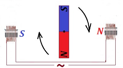
As a rotor approaches with its poles the poles of a stator, X and Y
should gradually weaken and, when the permanent magnet is fully aligned
along XY line, the magnitudes of the magnetic fields of electromagnets
should diminish to zero (X=0, Y=0).
Permanent magnet rotor will pass this point by inertia and the polarity of the electromagnets switches, so now X=N and Y=S.
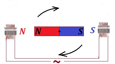
That causes rotation to continue until the permanent magnet of a rotor again takes a position along XY line.
By that time the electromagnets will be at X=0 and Y=0, rotor will
continue rotation by inertia, then AC switches the polarity of
electromagnets again and rotation continues in a similar manner
indefinitely.
Our first version of an AC motor is functional, but it has two obvious disadvantages.
One disadvantage is the usage of permanent magnet, they are very
expensive. We could not avoid it in a DC motor, but in an AC case we
might think that variable magnetic field might help to use the induction
effect to avoid it.
Another disadvantage is that switching the AC on does not really start
the rotation, we manually started it, and only then, if we gave a strong
push, it started to rotate and maintained this rotation.
Let's use a wire loop instead of a permanent magnet rotor. But, to act
as a permanent magnet, it needs an electric current running through the
wire, and we don't want any extra sources of electricity to connect to
it, it's complicated, needs a commutator, like in the original DC
motors.
Instead, we will count on the induction effect created by an alternating
current in a stator, which creates an alternating magnetic field,
which, in turn, induces the electric current in the wire loop of a
rotor.
The induced electric current in a wire loop of our rotor appears when a
wire crosses the magnetic field lines. Magnetic field produced by a
stator is directed always along a center line XY and is changing in
magnitude from a maximum in one direction (from X to Y) to zero, to a
maximum in another direction (from Y to X), again to zero etc.
The problem is, if the rotor is standing still, its wire does not cross
magnetic field lines. Therefore, no electric current will be produced in
it, and there will be no rotation. Rotor needs an initial push
sufficient to synchronize its rotation with the frequency of alternating
magnetic field to continue the rotation. Our second disadvantage is
still unresolved.
Let's imagine that, besides two main electromagnets with poles X and Y,
we have another pair of auxiliary electromagnets in a stator, that are
positioned perpendicularly to line XY. Let their poles be A and B and
(very important!) the current in them, also sinusoidal, is shifted in
time relatively to a current in main electromagnets by 90°.
So, when the magnetic field in one direction is maximum along line XY,
it's zero along line AB; then it gradually decreases along XY and
increases along AB until it's zero along XY and maximum along AB. This
cycle repeats itself indefinitely.
Graphically, it can be represented as follows.
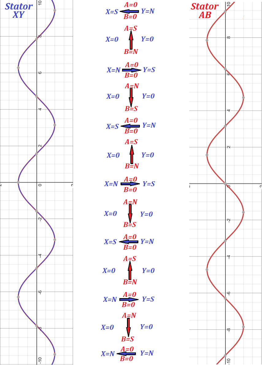
Graphs on the left and on the right of a picture represent the electric
current in each pair of electromagnets - XY and AB. Notice, they are
shifted by π/2=90°. The middle part of a picture represents the
direction of the magnetic field created by both pairs of electromagnets
of a stator.
As the time goes, the magnetic field direction is rotating. The rotating
magnetic field around a closed wire loop of a rotor causes the rotor's
wire to cross the magnetic field lines of a stator, which, in turn,
causes induction of electric current in a rotor's closed wire loop,
which will act now as a permanent magnet, which is supposed to follow
the rotation of the magnetic field around it.
This causes the rotation of the rotor. The rotor's actual physical
rotation will follow the stator's magnetic field rotation, created
without any physical movement.
The rotor cannot go after the stator's magnetic field rotation exactly
synchronously because then there will be no crossing of magnetic field
lines. So, the rotor, after it reached the same speed as the stator's
magnetic field rotation, will lose its rotational momentum and slow
down. Then the rotor's wire, rotating slower than the magnetic field
around it, will cross the magnetic field lines, there will be induction
current in it, it's magnetic properties will be restored and it will try
to catch up with the stator's magnetic field rotation. This process
will continue as long as AC is supplied.
An obvious improvement is to use multiple wire loops as a rotor with
common axis of rotation. That will cause more uniform rotation.
What's remaining in our project of designing the AC motor is to create
another alternating current for the second pair of electromagnets in a
stator with a time delay of π/2=90° relatively to the main AC.
This problem is resolved and described in the previous lecture about AC
capacitors. If we introduce another circuit fed from the same AC source,
but with a capacitor in it, this circuit will have the alternating
current shifted in time exactly as we want. This current will go through
the second pair of electromagnets and both pairs will create a
revolving magnetic field.
The interaction between magnetic fields of a stator and a rotor is quite
complex, when the rotor rotates. The magnetic flux going through a
rotor wire loop depends on a variable magnetic field of a stator and
variable area of a rotor wire loop in a direction of a magnetic field
lines of a stator. The exact calculations of this process are beyond the
scope of this course.
The main idea, however, is clear - to create an AC motor we have to create a revolving magnetic field - the great idea of Nicola Tesla. That can be accomplished by using known methods described above.

No comments:
Post a Comment