Notes to a video lecture on http://www.unizor.com
Alternating Current Induction
The Faraday's Law of electromagnetic induction states that a variable magnetic flux Φ(t) going through a wire loop generates in this wire loop an electromotive force EMF=U(t) equal in magnitude to a rate of change of the magnetic flux:
U(t) = −dΦ(t)/dt
where the meaning of the minus sign was explained in the lecture about self-induction previously in this course.
There are different ways to generate a variable magnetic flux. For
example, we can physically move a permanent magnet through or around a
wire loop, which will generate EMF in the wire.
But, having alternating current (AC) at our disposal and knowing
that any electric current creates a magnetic field around it, we can
create a variable magnetic field just by running AC through a wire.
Let's start from a simple experiment just to demonstrate the principle of AC induction.
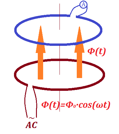
Here the bottom wire loop (we will call it primary) is connected to a source of an alternating current, while the top wire loop (secondary)
has no source of electricity, but is connected to a device to measure
the effective electric current in it - an AC ammeter (or amp-meter, or
ampermeter).
Since the AC in the primary loop is variable (more precisely, sinusoidal), the intensity of the magnetic field generated by it is also variable.
Therefore, the magnetic flux going through the secondary loop is
variable (also sinusoidal) with the generated EMF (first derivative of
magnetic flux) not equal to zero and also sinusoidal since the
derivative of sin(x) is cos(x) and derivative of cos(x) is −sin(x), as we know.
Variable (sinusoidal) EMF in the secondary loop causes the variable
(sinusoidal) electric current in it, which we can observe on the AC
ammeter.
We have just demonstrated the principle of AC induction -
transformation of the alternating electric current from one circuit
(primary loop) to another (secondary loop) without physical connection
between them.
Let's switch to more practical aspects of AC induction.
Recall from the earlier presented lecture "Magnetism of Electric Current in a Loop" that the intensity B of a magnetic field at the center of a wire loop in a vacuum equals to
B = μ0·I/(2R)
where
μ0 is the permeability of free space,
I is the electric current going through a wire loop (maybe variable as in the case of AC),
R is the radius of a wire loop.
If, instead of a vacuum, we have some other material inside a loop, the
intensity of a magnetic field will be different. The formula will be
almost the same, just the permeability of free space μ0 should be replaced with permeability of the corresponding material μ.
Experimentally obtained data tell us that one of the greatest permeability
is that of so-called ferromagnetic materials - those that contain iron.
Actually, pure iron has the permeability of about 200,000 greater than
vacuum. So, if we have a ferromagnetic material inside the primary wire
loop in our experiment, the magnetic energy will have a choice - to go
through highly resistant space around this ferromagnetic material or to
go through it with much less resistance.
The general principle of field propagation is that the most energy goes
through least resistance. So, we can expect that ferromagnetic material
inside the wire loop will concentrate the magnetic field generated by a
primary wire loop and much less of the field energy will be dissipated
around it.
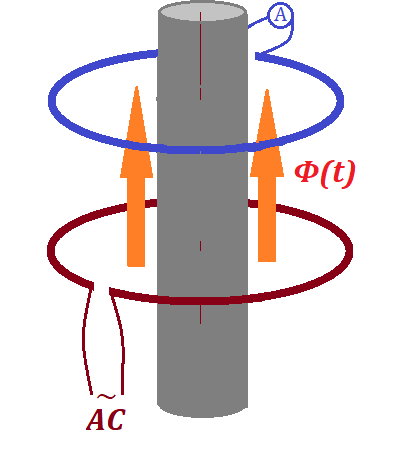
Our first improvement to the experiment above is to use a cylinder made of ferromagnetic material going through both our loops.
Ferromagnetic material has temporary magnetic properties and quickly
reacts to external magnetic field by rearranging the orientation of its
atoms. The variable magnetic field created by AC inside the primary loop
will force the atoms inside this cylinder to react by orienting along
the vector of intensity of the magnetic field, thus increasing this
intensity.
So, the purpose of this ferromagnetic cylinder going through both loops
is to increase the intensity of the magnetic field going through the
secondary wire loop without spending any more energy. The ferromagnetic
cylinder just concentrates and directs more of the energy of the
magnetic field to go through the secondary wire loop and less will be
dissipated outside the secondary loop.
Still, the energy of magnetic field generated by the primary wire loop
and directed through the ferromagnetic cylinder through both loops will
be dissipated from the ends of this cylinder.
To make our induction even more efficient, we can close the magnetic
field on the ends of a ferromagnetic cylinder as on this picture:
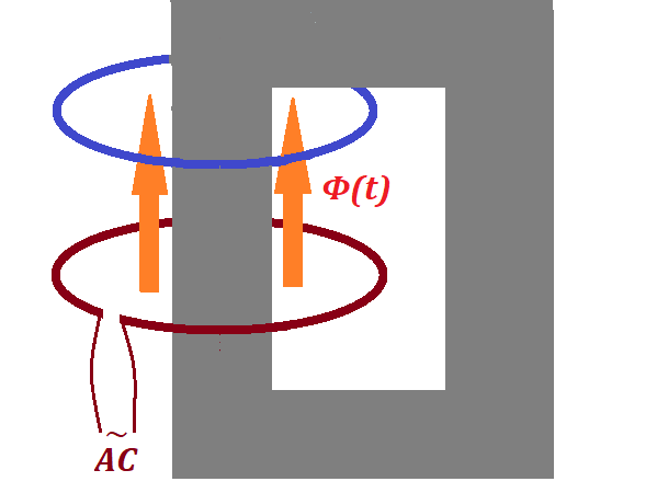
Now the magnetic field is not dissipated outside the ferromagnetic
material, and almost all energy generated by the primary wire loop with
AC running through it is used to create the magnetic flux inside the
secondary wire loop.
Our next practical improvement is related to the fact that the vector of
intensity of a magnetic field is an additive function. That is, the
intensity of a combined magnetic field of two or more sources equals to a
vector sum of intensities of all component fields.
We can use multiple loops in the primary coil, which is a source of
magnetic field, instead of a single primary wire loop in our experiment.
Let's wind NP primary loops of wire in a coil around
our ferromagnetic core. Connected to the same source of AC and having
the same sinusoidal current going through them, each loop will create a
magnetic field and all these NP fields will have to be added together to get the resulting magnetic field intensity.
So, the generated magnetic flux of such a coil will be NP times greater than the one by a single loop. Its inductive effect on the secondary wire loop will be NP times stronger.
As the next practical improvement of our experiment, let's use a coil of NS wire turns instead of a single secondary loop.
Each turn of this secondary winding will have the same magnetic flux
flowing through it and will induce an electromotive force (EMF)
proportional to a rate of change of magnetic flux. All these EMF in each
turn of a secondary wire are sequential to each other and should be
added together to get the resulting EMF in the secondary circuit.
So, the EMF induced in a secondary coil of NS wire turns will be NS stronger then the EMF induced in a single secondary loop.
So, changing the number of turns in the primary wire coil NP,
we proportionally change the variable magnetic flux, which, in turn,
proportionally change the induced EMF in the secondary coil.
Analogously, changing the number of turns in the secondary wire coil NS, we proportionally change the induced EMF in this wire coil.
These two facts lead us to use the device we have constructed to
transform the EMF of alternating current for whatever purpose we need.
Indeed, if NP=NS and our device is
ideal in a sense that the energy does not dissipate and the coils are
not heated up because of internal resistance, the same magnetic flux
goes through the same coils, which means the EMF in both primary and
secondary coils is the same.
If we want to induce the secondary EMF twice as stronger as the primary
one, we can double the number of turns in the secondary coil.
If we want to induce the secondary EMF twice as weaker as the primary
one, we can reduce the number of turns in the secondary coil by half.
This can be expressed as
UP(t)/US(t) = NP/NS
where
UP(t) is the EMF in the primary coil,
US(t) is the EMF in the secondary coil,
NP is the number of wire turns in the primary coil,
NS is the number of wire turns in the secondary coil.
But changing the EMF has its consequences.
The Conservation of Energy Law is still supposed to be held. The power
produced by AC in the primary coil in an ideal transformer is completely
transferred to the secondary coil, which means
P(t) = UP(t)·IP(t) = US(t)·IS(t)
where
P(t) is the power produced by primary and transferred to secondary coil, variable for AC,
UP(t) is the EMF in the primary coil,
IP(t) is the electric current in the primary coil,
US(t) is the EMF in the secondary coil,
IS(t) is the electric current in the secondary coil.
From the equation above follows that increasing the EMF in the secondary
coil causes proportional decreasing in the electric current in it and
vice versa:
UP(t)/US(t) = IS(t)/IP(t)
The formulas above are the basic principle of working of transformers -
devices used to increase the AC voltage, while proportionally decrease
the electric current and, therefore, decrease losses related to
transmission of electricity along long wires and also used to decrease
this voltage, while proportionally increase the electric current at the
location of homes and electric devices that need the lower voltage in
the outlets with higher amperage.

No comments:
Post a Comment