Notes to a video lecture on http://www.unizor.com
Three Phases AC
The Basic Principle
of 3-Phase AC Generation
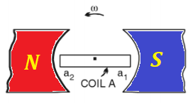
Recall the process of generating alternating current (AC) using a pair
of permanent magnets and a wire frame (a coil) rotating around the axis
perpendicular to magnetic field lines.
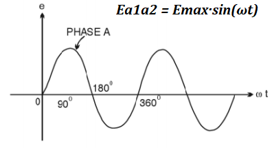
The pictures below represent the schematic design of such a system and a
graph of an electromotive force (EMF) generated between the ends a1 and a2 of the wire frame
Ea1a2 = Emax·sin(ωt)
where
Emax is the maximum absolute value of EMF,
ω is the angular speed of rotation of the wire frame,
t is time.
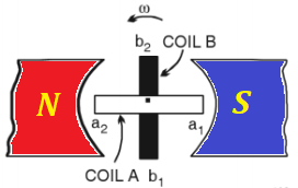
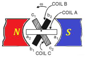
An obvious improvement to this design is to use the power of rotation
more efficiently by having two wire frames on the same axis positioned
perpendicularly to each other. In this case we can have two independent
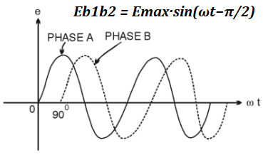
sources of EMF with the only difference of one of them to be shifted in
time relatively to another by 1/2 of the time of rotation.
This shift is related to a simple fact that at the moment one wire
frame, aligned along the magnetic line, crosses these magnetic lines
with the highest rate, while another wire frame, that is perpendicular
to magnetic field lines, moves along these lines without actual
crossing. Then the roles are changed, as the coils rotate.
The EMF between the ends b1 and b2 of the second wire frame will then be
Eb1b2 = Emax·sin(ωt−π/2)
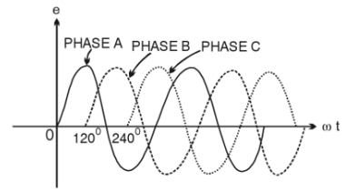
Why stop at two wire frames? Let's have three coils positioned at 120°
relative to each other. Now we will have three independent sources of
EMF shifted in time from each other by 1/3 of the time of rotation (phase
shift) - the time needed by one wire frame to take the position between
the magnet poles, previously taken by another wire frame.
Three different EMF, therefore, will be equal to
Ea1a2 = Emax·sin(ωt)
Eb1b2 = Emax·sin(ωt−2π/3)
Ec1c2 = Emax·sin(ωt−4π/3) = Emax·sin(ωt+2π/3)
Practical Implementation
The design of a three phase generator, as depicted above, is just the
first try of an idea. If the magnet is fixed and three wire frames
(coils) are rotating between its poles, it presents a problem to connect
these coils to transmit the generated electricity to consumers, we need
sliding contacts, brushes and other impractical devices.
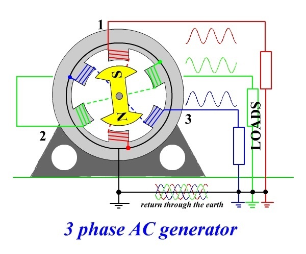
In real life generators the three coils make up a stator - a fixed part
of a generator, while the magnet is rotating inside a circle of coils by
external power (like steam, water, wind etc.), generating the
alternating current in the coils, which allows to make an electric
connection to coils fixed.
At the first glance, three coils have three pairs of connections with
sinusoidal EMF generated in each pair and, to transfer AC electricity
from all coils to consumers, we seem to need three pairs of wires, two
from each coil - six wires altogether. This, however, can be improved by
using the following technique.
Let's connect ends a2, b2 and c2
of three coils together (see a picture below, it's a black wire at the
bottom connected to a black circle going around all coils) and see what
kind of resulting voltage will be observed on each end of the coils.
This is called a star connection of the generator's coils.
We know that the electric potential (EMF) on each of the above contacts
has a sinusoidal magnitude with a time shift by 1/3 of a period relative
to each other. When we connect these three contacts, the potential at
the joint will be
E0 = Emax·sin(ωt) + Emax·sin(ωt−2π/3) + Emax·sin(ωt+2π/3) = Emax·X
where
X = sin(ωt) + sin(ωt−2π/3) + sin(ωt+2π/3) =
= sin(ωt) + sin(ωt)·cos(2π/3) − cos(ωt)·sin(2π/3) + sin(ωt)·cos(2π/3) + cos(ωt)·sin(2π/3) =
= sin(ωt) + sin(ωt)·(−1/2) − cos(ωt)·(√3/2) + sin(ωt)·(−1/2) +
cos(ωt)·(√3/2) = 0
Therefore, E0 = 0
There will be no difference in electrical potential between the joint and the ground.
This fact enables to transmit all three phases of generated electricity along four wires - one from a1 (phase 1) contact, one from b1 (phase 2) contact, one from c1 (phase 3) contact and one neutral from a joint connection to a2, b2 and c2.
The neutral wire is usually grounded since its electric potential is equal to zero.
With this arrangement we still have an advantage of having three
independent phases of alternating current, but we need only four wires
to transmit it - three phase wires and one neutral.
Connecting any device to any phase and a neutral wires, we will get a closed circuit with AC running in it.
Energy Consideration
Obviously, putting two or three coils in a stator of a generator doubles
or triples the energy output carried by outgoing wires. The Law of
Energy Conservation must work, so where is the energy is coming from?
Recall the electromagnetic induction experiment described in the lecture
"Faraday's Law" in the "Electromagnetic Induction" chapter of this
course with a wire moving in the uniform magnetic field.
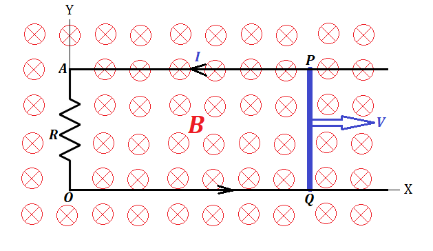
Since we physically move wire's electrons in one direction
perpendicularly to magnetic field lines, the Lorentz force pushes them
perpendicularly to both, the direction of the movement of a wire and the
direction of the magnetic field lines, that is, along the wire, thereby
creating an electric current between wire ends.
Now electrons are moving with a wire in one direction and along the wire in another.
The first movement maintains the electric current in the wire, but the
second, again, is a subject of the Lorentz force that pushes the
electrons perpendicularly to their direction, that is opposite to the
original direction of a wire movement.
This force resists the movement of a wire in its original direction. We
have to perform work against this force to move the wire.
Similar considerations are true in a case of a circular movement of a
wire frame in a magnetic field or, if wire coils are in a stator, the
force is needed to rotate the magnet in a rotor. That is, we have to
spend energy to generated the electricity, the rotor's rotation is
possible only if we apply the force against the Lorentz forces resisting
this rotation. The magnetic field generated by the electric current in a
wire coil of a stator resists the rotation of a magnet in a rotor.
If we have more than one coil in a stator, each one resists the rotation
of a rotor, so we have to spend proportionally more effort to rotate
the rotor.
The Law of Energy Conservation works. The more coils we have in a stator
- the more electricity is generated, but the more resistance to a
rotor's rotation needs to be overcome.
Three Phase AC Motor
The lecture "AC Motors" of this chapter described the necessity of having a rotating magnetic field to make an AC motor.
To achieve such a rotating field we had to resort to artificially create
a second AC current with a phase shift by 90° using a capacitor or a
transformer.
Most of household AC motors (like in a fan) work on this principle, they need only two wires, which are, as we can say now, a phase wire and a neutral one.
Powerful industrial level AC motors (like in a water pump that works in a
tall building to pump water to the roof tank) needs more power, and we
can use all three phases to create a rotating magnetic field.
So, all four wires coming from the AC generator, three phase wires and one neutral
one go into an AC motor, whose principal construction very much
resembles the one described in the previous lecture. The only difference
is, we already have three wires with AC phase shifted by 120°
relatively to each other. So, we have to position three wire coils in a
stator at 120° angles to each other, connect one end of each coil to a
corresponding phase wire and another end - to a common neutral
wire, and the rotating field is ready. Then it will work pretty much as
it was described in the "AC Motors" lecture, but smoother because three
phases make a smoother rotation of a magnetic field than two phases.
At the end I would like to say again, that it was Nicola Tesla's genius
that created all the basic principles, based on which all the current AC
motors are working now. His contributions to our industrial development
are grossly underappreciated. Calling an electric car model "Tesla" is a
late but well deserved tribute to his creativity.


No comments:
Post a Comment