Problems on LC Circuit
Problem A
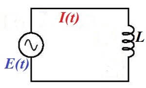
Consider a circuit that contains an AC generator, an inductor of inductance L and a capacitor of capacity C in a series.
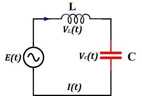
Generated EMF has frequency f=50Hz and effective voltage Eeff=220V (volt).
The effective AC current is Ieff=5A (ampere).
The capacitance of a capacitor is C=10μF (microfarad).
Find inductance L (henry) of an inductor?
Solution
Let's start with an expression for the AC current in the LC circuit in terms of generated EMF and reactance of the capacitor and inductor.
EDF generated by a source of electricity
E(t) = E0·sin(ωt)
where
E0 is a peak voltage on the terminals of a generator,
ω=2πf is an angular velocity of a rotor in radians per second, where f is a frequency of generated EMF in number of cycles per second.
Alternating electric current in the circuit
I(t) = I0·cos(ωt)
where
I0 = E0/(XC−XL) is peak amperage,
XC = 1/(ω·C) is capacitive reactance,
XL = ω·L is inductive reactance
Effective voltage and effective amperage are less than, correspondingly, peak voltage and peak amperage by √2.
Therefore, from the expression for AC current follows
I(t) = I0·cos(ωt) =
= E0·cos(ωt)/(XC−XL)
Ieff = I0/√2 =
= E0/[√2(XC−XL)] =
= Eeff/(XC−XL)
The unknown in this expression is XL that can be found:
XC−XL = Eeff/Ieff
XL = XC−Eeff/Ieff
Since XC=1/(ω·C) and XL=ω·L L·ω = 1/(ω·C) − Eeff/Ieff
L = 1/(ω²·C) − Eeff/(ω·Ieff)
Substituting
ω=2πf=2π·50Hz=314(1/sec)
C=10μF=10−5F
Eeff=220V
Ieff=5A
into above expression for L, we obtain (rounded to 0.001)
L= 1/(314²·10−5)−220/(314·5)=
= 0.874H (henry)
Problem B
Consider a circuit that contains a source of a noisy electrical signal, which is a combination of many sinusoidal waves with different frequencies, amplitudes and phase shifts, a resistor with resistance R and a capacitor with capacitance C connected parallel to a resistor.
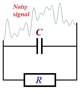
The signal (electrical current) coming through a resistor will have higher frequencies weakened by a presence of a capacitor.
Explain why.
Explanation
Reactance of a capacitor XC, which functionally similar to a resistance of a resistor, is inversely proportional to a frequency of the voltage on its ends
XC = 1/(ω·C) = 1/(2πf·C),
where
ω=2πf is the angular velocity of oscillations,
f is a frequency of oscillations,
C is the capacitance of a capacitor.
Therefore, the greater frequency - the less reactance of a capacitor.
Since reactance of a capacitor is functionally similar to a resistance of a resistor, this circuit is similar to a circuit with two parallel resistors with one of them having lower resistance with higher frequencies of the oscillations of the electrical current.
Using this analogy, we see that higher frequency oscillations of the electric current going through a capacitor will meet less resistance than lower frequency oscillations. Therefore, higher frequency oscillations of the current will go easier through a capacitor, thus having less impact on a resistor.
More precisely, the current going through parallel resistors is inversely proportional to their resistance (see lecture "DC Ohm's Law" in this part of the course). This is true not only for constant direct current produced by constant EMF E, but also at any moment t, when generated EMF oscillates (even irregularly) as a function of time E(t).
Therefore, a capacitor will lower reactance will have higher current going through it, thus weakening the higher frequency oscillations of the current going through a resistor.
Problem C
Consider a circuit that contains a source of a noisy electrical signal, which is a combination of many sinusoidal waves with different frequencies, amplitudes and phase shifts, a resistor with resistance R and an inductor with inductance L connected parallel to a resistor.
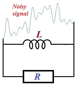
The signal (electrical current) coming through a resistor will have lower frequencies weakened by a presence of a inductor.
Explain why.
Explanation
Reactance of an inductor XL, which functionally similar to a resistance of a resistor, is proportional to a frequency of the voltage on its ends
XL = ω·L = 2πf·L,
where
ω=2πf is the angular velocity of oscillations,
f is a frequency of oscillations,
L is the inductance of an inductor.
Therefore, the lower frequency - the less reactance of an inductor.
Since reactance of an inductor is functionally similar to a resistance of a resistor, this circuit is similar to a circuit with two parallel resistors with one of them having lower resistance with lower frequencies of the oscillations of the electrical current.
Using this analogy, we see that lower frequency oscillations of the electric current going through an inductor will meet less resistance than higher frequency oscillations. Therefore, lower frequency oscillations of the current will go easier through an inductor, thus having less impact on a resistor.
More precisely, the current going through parallel resistors is inversely proportional to their resistance (see lecture "DC Ohm's Law" in this part of the course). This is true not only for constant direct current produced by constant EMF E, but also at any moment t, when generated EMF oscillates (even irregularly) as a function of time E(t).
Therefore, an inductor will lower reactance will have higher current going through it, thus weakening the lower frequency oscillations of the current going through a resistor.
SUMMARY
Capacitors and inductors can be used to filter certain "useful" frequencies from the noisy signals.