Notes to a video lecture on http://www.unizor.com
Direct Current - Ohm's Law
Simply speaking, experiment shows that the current in a conductor (amperage) is proportional to a difference in potentials (voltage) on its ends. This is the Ohm's Law.
Obviously, some physical explanation of this law is appropriate, and this is what this lecture is about.
Electric current is the flow of electrons inside a conductor. Just as a reminder, the traditionally defined direction of the current is opposite to the direction of the flow of electrons.
Even without any electric field electrons inside a conductor are not exactly spin each around its own nucleus, staying on the orbit forever. Some of them, especially those on the outer orbit, can tear off their orbit, jump to another nucleus' orbit, then going somewhere else etc., thus creating certain chaotic environment.
When an electric field is present, the chaotic movement of electrons becomes directional to a degree, depending on the strength of the field, thus creating a flow of electrons - an electric current.
This flow of electrons occurs when there is an excess of electrons on one end and deficiency (or less of an excess) of electrons on the other end, which creates an electric field inside a conductor that forces some light electrons to leave their atoms and move, while heavy nuclei with remaining electrons stay put.
Electrons are repelled from the end, where there is excess of them and attracted (or repelled less) from the other end.
On their way from one end of a conductor to another these electrons must go through a maze of atoms, many of which have lost some electrons because of the electric field and, therefore, are positively charged, attracting negative electrons in an attempt to compensate lost electrons. Some succeed by capturing free electrons, some not, some lose more electrons in their chaotic but directional movement.
The flow of electrons inside a conductor can be compared with a waterfall from the high level, where potential energy relative to gravitational field of the Earth is greater to a lower level with lesser potential energy.
As water falling down the waterfall, hitting all the stones on its way, electrons hit atoms and lose some of their energy, some of them get absorbed by atoms and don't reach the other end of a conductor, thus diminishing the flow.
The very important aspect in this movement of electrons is the properties of the material a conductor is made of.
Different atoms of different materials have different characteristics of capturing and releasing electrons, when subjected to the forces of an electric field. However, certain common laws of conductivity can be logically explained and used in practical applications.
Ohm's Law
Stronger electric field produced by a greater difference in electric potential (voltage U) between the ends of a conductor should cause more intense movement of electrons, greater number of electrons going from one end of a conductor and reaching the other end per unit of time (amperage I). This qualitative property is perfectly understood. Mathematically speaking, I is a monotonically increasing function of U.
It was an experimental fact that this monotonic function to a very high precision is linear:
I = σ·U
where σ is called a conductivity of a conductor.
In more common cases this law is written not in terms of conductivity, but in terms of resistivity:
I = U / R
where R is called a resistance of a conductor.
In most cases we will use the Ohm's Law in that last form, using a resistance as the characteristic of a conductor.
Resistance
In practical life we use some conductors with a very low resistance, like copper wire, to connect some electrical appliance, like a regular incandescent lamp bulb, to a source of electric power. In this arrangement we usually consider wiring as having no resistance and concentrate on the properties of an appliance as the one with the electrical resistance R.
Schematically, resistor is pictured as a rectangle or a zigzag line connected by straight lines of wires to a source of electric power
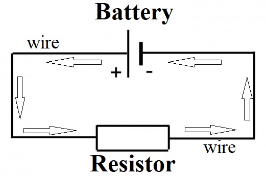
Arrows on this picture show the traditionally defined direction of electricity from positive to negative terminal of the source of electric power - opposite to a direction of electrons' movement.
Consider an extreme case when the resistor is non-conductive, like there is only vacuum in between its two ends. Symbolically, it's equivalent to R=∞. The Ohm's Law in this case results in I=U/R=0, which means that the circuit is broken and there is no current in it.
In an opposite extreme case with R=0 we have I=U/R=∞, which is the so called "short".
In practical life it happens when you detach two wires coming to a lamp and connect them. Without the bulb, which has some significant resistance, the electric current in a circuit would almost instantaneously grow very high and you might get electrocuted.
Let's use an incandescent lamp as an example of a resistor. More precisely, the resistor is a tangent spiral (filament) inside the lamp.
Consider what happens with the resistance of this tangent spiral if we will make it longer.
Obviously, the electrons will have to go through more obstacles on their way from one end of a spiral to another, which will slow their movement more than when a spiral was shorter. It's logical to expect that doubling the length of a resistor will double its resistance, and it is confirmed by experiments.
In general, for linearly-shaped resistors their resistance should be proportional to the length.
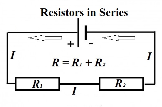
The immediate consequence of this consideration is that two resistors, sequentially connected one after another in a series, will have a combined resistance equal to a sum of resistance of each one.
Now, instead of making a spiral longer, let's make it thicker. Electrons will have more space to move, more freedom of direction and more electrons can travel across the spiral per unit of time. Doubling the thickness of a spiral is similar to doubling the width of a highway with more cars moving on it per unit of time. So, the resistance of a thicker spiral will decrease by the factor of increased cross-section area of a tangent spiral.
In general, for linearly-shaped resistors their resistance should be inversely proportional to the cross-section area.
Increasing the thickness of a spiral is logically equivalent to using two spirals connected parallel to each other, as on this circuit diagram.
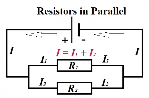
The number of electrons per unit of time (electric current or amperage) coming from the common wire is split into two parallel flows, and all the electrons passing through a common part of a circuit per unit of time should be equal to a sum of numbers of electrons passing through each of the parallel segments.
The immediate consequence of this consideration is that two resistors, connected parallel to each other, will result in the electric current in a common wire to be a sum of electric currents in each one of them.
I = I1 + I2
Now let's apply the Ohm's Law to an entire circuit, and each of two parallel branches, keeping in mind that the voltage between the terminals of the battery is U, the same as the voltage between the ends of each resistor, and the resistance of each branch is known as R1 and R2.
Assuming the total resistance of two parallel branches is R, the Ohm's Law gives
I = U / R
Applying the same principle to one branch with resistor R1, we have
I1 = U / R1
The same for another branch:
I2 = U / R2
Now the original equation about a current in the common segment of a wire equaled to a sum of currents in two branches looks like
U / R = U / R1 + U / R2
or
1/R = 1/R1 + 1/R2
From the last equation follows the expression for a combined resistance of two resistors installed parallel to each other
R = 1 / (1/R1 + 1/R2)
This formula looks more cumbersome and the one for 1/R above is more commonly occurs.
Instead of resistance, it can be expressed in terms of conductivity of an entire assembly σ=1/R of two parallel resistors with conductivity σ1=1/R1 and σ2=1/R2:
σ = σ1 + σ2
For two identical resistors of resistance r each the combined resistance R would be
1/R = 1/r + 1/r = 2/r
R = r/2
More generally, we can derive the resistance of n identical resistors of resistance r each connected parallel to each other. In this case the electric current I in the common wire in split into n identical flows, each having an amperage of I/n. From the Ohm's Law the voltage at the ends of each resistor should be U=I·r/n, from which follows that R=r/n is the resistance of an entire assembly of n identical resistors with resistance r each.
Example
Consider a circuit with resistors R1 and R2 connected parallel to each other and resistor R3 installed after both of them in a series.
What would be the resistance R of a combined assembly of these three resistors?
First, determine the resistance of two parallel resistors as a unit.
R12 = 1 / (1/R1 + 1/R2)
This this unit of two parallel resistors with resistance R12 is in a series with resistor R3, their combined resistance is the sum of their individual resistances
R = R12 + R3 = [1 / (1/R1 + 1/R2)] + R3
Resistance Units
of Measurement
The Ohm's Law allows to easily establish the units of measurement for the resistance of any component in an electric circuit - ohms Ω.
From the original form of the Ohm's Law
I = U / R
follows that
R = U / I
This allows to establish a unit of measurement for resistance of any component of an electric circuit.
If the difference in potential (voltage) between one end of such a component and another is 1V (volt) and the electric current going through it is 1A (ampere), this component by definition has a resistance of 1Ω (ohm).
Consequently, the resistance of a component in an electric circuit with the current going through it I (ampere) with voltage on its end U (volt) equals to U / I (ohm).

No comments:
Post a Comment