Electronic Oscillator
From the "Electromagnetism" part of this course we know that variable (sinusoidal) oscillations of electric current in the wire frame can be induced by rotating this frame in the magnetic field.
Using the terminology of the mechanical oscillations, the oscillations of the electric current in such a case should be called forced.
There are, however, circuits where oscillations of electric current are free from any external forces.
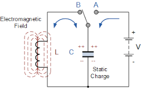
Let's consider the following simple circuit that contains a battery, a capacitor C and an inductor L, ignoring for now an electrical resistance of a circuit.

The above is the LC-circuit because it consists of an inductor and a capacitor.
When an AB-switch is in the A position, the capacitor will be charged from a battery.
Now we switch to the B position, battery is no longer a factor, and capacitor is charged.
Initially, the voltage between the plates of a capacitor is at maximum, so the electric current is at maximum as well.
As the charge goes from one plate to another through an inductor, the voltage and the electric current are diminishing sinusoidally from some maximum at time t=0 to zero at t=T/4, where T is a period.
Assume (and the supporting calculations of the validity of this assumption follow), the electric current is diminishing with time t as
I(t) = I0·cos(ωt)
where
I0 is the maximum value of a current
ω is angular speed
T = 2π/ω is a period
The speed of change of the current is the first derivative of this function
dI/dt = −I0·ω·sin(ωt)
This speed of change also changes with time sinusoidally, but its maximum at t=T/4 coincides with minimum of the current itself.
As we know, the change in the current in the inductor causes the change of the magnetic field around it, which, in turn, causes the appearance of a self-inducted electromotive force. You can refer to "Self-induction" chapter of the "Electromagnetism" part of this course for details.
The electromotive force is stronger, when the speed of change of the magnetic field is stronger, and it forces the electric current to continue its existence even after one plate of the capacitor lost its charge to another plate.
The maintained by the magnetic field current will make the capacitor to be charged again, but in opposite direction (the plate, that used to positive, now is negative and vice versa).
As the charge accumulates on the capacitor, it slows down and stops the flow of the current induced by a changing magnetic field. When the current is stopped, the situation resembles the one at time t=0, but with reversed charges on the capacitor's plates. So, the current starts flowing again, but in opposite direction.
The internal resistance R of a circuit will result in some lost energy and, therefore, the maximum charge on the plates of a capacitor will diminish with time. This exactly resembles damped mechanical oscillations.
Let's get into some theory of this LC-circuit without taking into consideration the internal resistance of a circuit.
Assume that the current in a circuit is I(t), the voltage drop between the plates of the capacitor is VC(t) and the voltage drop on the inductor is VL(t).
By definition of the capacitance C of a capacitor,
C = Q(t)/VC(t) or
C·VC(t) = Q(t)
where Q(t) is the charge on its plates at time t.
We prefer to deal with the electric current I(t), which is defined as amount of moving charge per unit of time, which is mathematically expressed as a derivative of charge by time,
I(t) = dQ(t)/dt
Differentiating the above equation between voltage and charge on a capacitor, we obtain the dependency between voltage and current on a capacitor:
C·dVC(t)/dt = I(t) or
V'C(t) = I(t)/C
Any current that goes along a wire creates a magnetic field around this wire. Since the electric current in our inductor is variable, the magnetic field that is generated by this current is variable.
According to the Faraday's Law, the variable magnetic field going through a wire loop generates EMF equal to a rate of change of the magnetic field flux.
Therefore,
VL(t) = dΦ(t)/dt or
VL(t) = Φ'(t)
In turn, magnetic flux Φ(t) going through inductor, as a function of time t, is proportional to an electric current I(t) going through its wire
Φ(t) = L·I(t)
where L is a coefficient of proportionality that depends on physical properties of the inductor called inductance of the inductor.
From this we derive the following equation for VL(t):
VL(t) = L·I'(t)
Finally, since the circuit contains no sources of electrical energy, sum of all voltage drops should be equal to zero:
VC(t) + VL(t) = 0
Now we have the following system of three differential equations with three functions:
V'C(t) = I(t)/C
VL(t) = L·I'(t)
VC(t) + VL(t) = 0
Differentiating the third equation by t and substituting voltages through their expressions in terms of electric current, we obtain
I(t)/C + L·I"(t) = 0 or
I"(t) + I(t)/(L·C) = 0
The last equation resembles the one that describes harmonic mechanical oscillations of an object on an ideal spring
x"(t) + (k/m)·x(t) = 0
where
x(t) is a displacement of an object on a spring from the neutral position,
k is a spring's elasticity and
m is an object's mass.
The general solution to the above equation, as we have shown, when considered the periodic mechanical oscillations, is
x(t) = C1·cos(ω·t) + C2·sin(ω·t)
where
ω² = k/m
C1 is initial displacement of the object from the neutral position of equilibrium
C2 is defined by the initial velocity of an object and is zero, if there is no initial velocity.
Analogously, the general solution of our differential equation for the electric current in an LC-circuit is
I(t) = C1·cos(ω·t) + C2·sin(ω·t)
where
ω² = 1/(L·C)
C1 and C2 are defined by initial conditions.
The period of these oscillations of electric current in the LC-circuit is
T = 2π/ω = 2π√L·C
This is known as the Thomson's formula.


No comments:
Post a Comment