Friday, January 29, 2021

Electricity to Consumers: UNIZOR.COM - Physics4Teens - Electromagnetism ...

Notes to a video lecture on http://www.unizor.com

Distribution to Consumers

When we described the grid in the previous lecture, we concentrated on main principles of its work - synchronization of the generators of electric energy with the grid. It might make a wrong impression that the grid is one gigantic wire that have certain voltage, frequency and phase, and all the generators must adhere to this standard, when connected to it.
The real situation is more complex.

Considering the grid covers large distances, we must maintain the high voltage in it to avoid waste of energy to heat (hundreds of thousands of volts). Most consumers, however, need relatively lower voltage (no more than a few hundred volts).

To connect each consumer to a grid through a powerful and very expensive transformer is impractical. Instead, we combine a group of geographically close consumers into it's own grid, connected at one point to a main ultra high voltage grid through a transformer that lowers the voltage, and then we connect consumers to this second level grid.

For example, the whole city can form this secondary grid with lower voltage than in the main ultra high voltage grid. Thus formed, this secondary grid can go to each street with lower voltage better suitable for consumption. And, because this grid is relatively localized, there will be no big loss of energy to distribute electricity at a lower voltage.

Making the picture even more complex, we can arrange third level grid lowering the voltage for each building in the city from street level of the secondary grid to a lower voltage building level that goes to each apartment.

Yet another complication can be introduced by connecting other generators to a grid. Since our grid now consists of many grids connected via transformers from main ultra high voltage to second level with lower voltage in the city and third level for each building, we can introduce generators into each grid, and the only requirement for this is to make sure that each generator conforms to a corresponding grid's voltage, frequency and phase.

For example, a building's management decided to put solar panels on the roof. They generate electricity for a building and, if there is excess of energy, it goes to a grid for general consumption. That, probably, is the third level grid that serves this building, it has it's own characteristics, and the output of solar panels must conform to these characteristics.

Similarly, a city decided to build a power plant working on burning the garbage. This power plant produces electricity that should go to a grid that serves the whole city, which we call the second level grid. The voltage produced by this plant is higher than the one in any building level grid but not as high as in main ultra high voltage grid that supplies the whole city.

The overall picture of distribution of electricity consists of different grids of different voltage, connected through transformers, having producers and consumers in each grid. Each consumer of electricity should have its parameters to be the same as the grid it's connected to (voltage and frequency). Each producer of electricity should be synchronized with the grid it's connected to in voltage, frequency and phase.

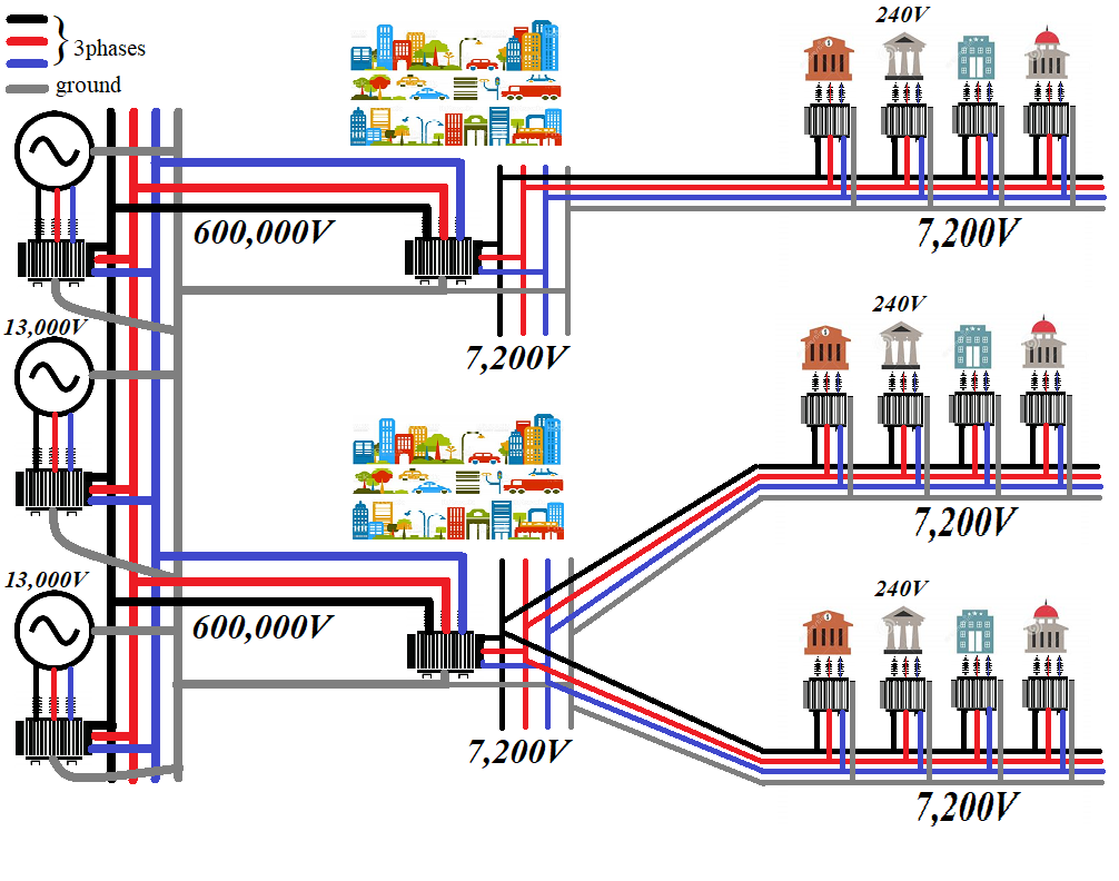
On the picture below we have schematically displayed the generation of electricity at 13,000V, transformers that increase the voltage to 600,000V to transmit along the long distances, transformers that decrease the voltage to 7,200V at the entrance to a city that supplies this electricity to buildings and, finally, transformers that decrease the voltage to 240V before entering buildings.
Inside the buildings this voltage is distributed to individual apartments.
In practice there are more devices participating in the grid, stabilizing the voltage, sensing the abnormal conditions, controlling different functions of the grid, protecting the grid against disastrous conditions, attacks or human errors etc.

The grid is constantly changing as new sources of energy come on line, new consumers are attached to a grid, new more efficient maintenance devices are introduced

Sunday, January 24, 2021

Electric Grid: UNIZOR.COM - Physics4Teens - Electromagnetism - Distribution


Notes to a video lecture on http://www.unizor.com

The Grid

The grid is an extremely important solution to most problems with electric power interruption due to different technical issues at power plants that generate electricity.

Consider a simple analogy of distributing water to apartments in a large building from a tank on a roof.
If you have one tank, and it needs repair or cleaning, the water to all apartments must be shut off while the work performed.
If, however, you have two water tanks on the roof both connected to a common distribution pipe, from which the water is flowing to all apartments, we can just close the connection of the tank to be cleaned to a distribution pipe, leaving another tank operational and water supply to apartments uninterrupted.

This same principle is used in combining many generating electricity power plants to a common distribution wiring, thus assuring uninterrupted power supply. This system of interconnected power plants forms a grid that feeds those consumers of electricity connected to it, assuring their uninterrupted work.

Obviously, with electricity it's much more complex than with water supply.

Let's enumerate problem we have to resolve when connecting different electric generators to a common power distribution system.

Direct Current

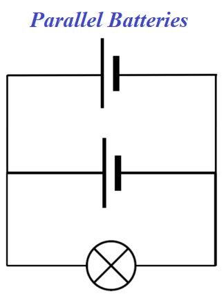
Let's connect two batteries generating direct current parallel to each other and power up a lamp.

The proper connection requires the same polarity (positive pole of one battery is connected to positive pole of another, negative - to negative) and the same voltage generated by these batteries. Only then there will be no electric current between the batteries, only from a battery to a device consuming the electricity (a lamp in this case).
These two conditions, similar polarity and equal voltage, are necessary and sufficient conditions to successfully connect two batteries in parallel. The overall energy capacity of these two batteries will be twice as big. They will last twice as long on the same load (one lamp) or they can double the load (have two lamps parallel to each other) and serve the same time as one battery on a single load.


Alternating Current

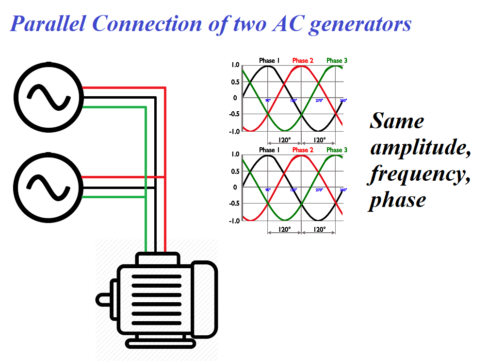
Analogously, two generators of alternating current (AC) must have the same output voltage, if connected in parallel. Otherwise, there will be an unnecessary electric current between them, which diminishes their usefulness.

But for AC generators there are more characteristic parameters than just a voltage. Voltage varies as a sinusoid with time and is characterized by amplitude, frequency and phase.

All three parameters must be the same for a proper parallel connection of two generators. Their output voltages, as functions of time, must coincide exactly to each other. And this is a big challenge to build a grid with many different generators, each contributing their part in overall power supply.


The above considerations dictate strict restrictions on how any new source of electricity, like a new power plant or a new solar panel are hooked to a grid.

First of all, the output of a generator at the point of connection to a grid must be alternating. Solar panels, for example, produce direct current, so, before connecting to a grid, the DC electricity must be converted to AC. Special devices called inverters provide this type of conversion, assuring the frequency of voltage oscillation to be that of the grid.

Then, depending on a point of connection to a grid, the output voltage must be equalized with that of the grid at the connection point. This can be done with proper transformers.

Finally, we have to adjust the phase to synchronize the output of the generator with the phase of a grid. This can be achieve by adjusting the speed of a generator's rotor while monitoring the phase difference on a special sensor until proper synchronization is achieved.

Overall, the connection to a grid is a sophisticated process that requires special devices, tools, instrumentation and care.
There are many controls that monitor, adjust and maintain the regime of work of a grid. In many ways it's automated, computer controlled and reliable. However, human errors do happen and some of them result in significant distortions of power supply to large areas and affecting a lot of people. As an example, the 2003 blackout in Ohio resulted in power loss across Eastern United States and even some areas in Canada.

Friday, January 22, 2021

Electricity In Transit: UNIZOR.COM - Physics4Teens - Electromagnetism - ...

Notes to a video lecture on http://www.unizor.com

Electricity in Transit

Let's discuss how electricity is delivered from the power plants to consumers.

The only way to deliver the electricity from the place it's generated to a place it's used is via electric wires.
Since the distance between the power plant and a consumer can be substantial, may be even hundreds of kilometers, the problem of losses of electric energy in transit because of wire resistance is extremely important.

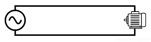
Examine a simple electric circuit consisting of a source of electricity (generator) and a consumer (like an electric motor).
In theory, we have four places where electric energy is spent:
(a) inside a generator due to internal resistance,
(b) inside a wire from a generator to a motor due to wire resistance,
(c) inside a motor due to useful work the electricity does and internal resistance,
(d) inside a wire from a motor back to a generator due to wire resistance.


Obviously, only in a motor the energy is spent with some useful purpose, in other places the energy is spent just because it's unavoidable, that is wasted.

Amount of energy wasted to heat per unit of time due to wire resistance Wwire depends on the current running through wire Iwire and the wire resistance Rwire according to a formula
Wwire = I2wire·Rwire

For practical example, let's calculate the amount of energy wasted in some long piece of copper wire.
The resistance of a wire depends on resistivity of material it's made of ρ, is proportional to the length of a wire L and is inversely proportional to its cross-section area A
Rwire = ρ·L/A

For copper the resistivity is approximately
ρ≅1.70·10−8 Ω·m.
Assume, the combined wire length to and from a consumer of electricity is
L = 1 km = 1000 m
and its diameter is
D = 2 mm = 2·10−3 m,
which gives the area of its cross-section
A = π·D²/4 ≅ 3.14·10−6 m²
Then the resistance of this peace of wire is
Rwire ≅ 5.4 Ω

For example, we are supposed to run an electric motor working at voltage
Umot=220 volt
and delivering power of
Wmot=2.2 kilowatt.

Then the current it requires is
Imot = Wmot/Umot = 10 A

The current Imot=10 A must go through the wire
Iwire = Imot = 10 A
Then the amount of energy wasted to heat in the copper wire of resistance Rwire=5.4 Ω per unit of time (a second) is
Wwire = I²wire·Rwire = 540 W

For a price of about $0.1 per kilowatt this amounts to about $0.054 per second. For 24 hours uninterrupted work the financial waste amounts to $4,665, and that is every day of operation of one motor, which is absolutely unacceptable.

Reducing the resistance of a wire by making it thicker or using multiple parallel wires has its practical limitations because of cost of wires. Therefore, our solution to reduce the energy wasted to heat due to wire resistance, while staying within reasonable limits with the cost of a wire, must be related to reducing the current Iwire running through a wire without reduction of power that is supposed to be delivered to consumers of electricity.

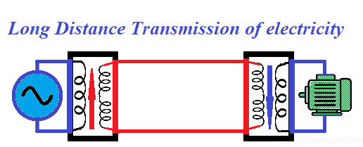
This can be accomplished by using transformers.
Immediately after generation, the alternating current is directed to a transformer that increases the voltage and proportionally decreases the amperage.

At the output of this transformer the voltage reaches thousands of volts - from low voltage of 1000V to ultra high voltage above 800,000V, depending on the length of wires from generators to consumers.
This high voltage electricity is delivered to consumers, where another transformers reduce the voltage to standard needed to run all their different devices.

Consumers of electricity get the voltage required to run their equipment, but the current running in the long wires between generators and consumers is low, thus reducing waste of electric energy.

Consider an example above with a motor that needs Wmot=2.2 kilowatt of electricity at voltage Umot=220 volt and, therefore, requires Imot=10 A electric current.
If, instead of transmitting electricity with these parameters, we increase the voltage by a transformer before sending it to long wires to, say, 2200V, thus proportionally reducing the amperage by the same factor, our amperage will be
A = W/U = 2200/2200 = 1A
Reducing the amperage from 10A to 1A reduces the energy waste by a factor of 100 because the heat formula depends on a square of amperage.

The distribution of electricity, therefore, should include transformers that increase the voltage before sending electricity along long wires and decrease it wherever it's needed for usage by consumers.
With this modification the picture that corresponds to practical aspects of distribution of electricity looks like this


To increase the electrical systems' reliability, improve the energy balancing and make sure of uninterrupted power supply, the sources of electrical energy (electric power plants and other installations producing electric energy) are combined into a network called the grid.
The principles of this networking are a subject of the next lecture.

Sunday, January 10, 2021

Electricity at Power Plants: UNIZOR.COM - Physics4Teens - Electromagneti...

Notes to a video lecture on http://www.unizor.com

Electricity at Power Plants

Addressing distribution of electricity, we will primarily discuss the way electricity, produced at the power plants, is delivered to consumers.
We will concentrate on the process of distribution of electricity generated from the kinetic energy of rotating turbines, as the most quantitatively significant source of electricity.

Three stages of this distribution are
(a) at the power plant
(b) in transit
(c) at consumers.

This lecture is about what's going on at the power plant that produces the electricity from the kinetic energy of rotating turbines.

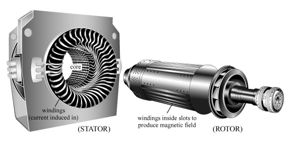
Turbines at electric power plants are rotated because of a flow of steam or water, or wind. Turbines are acting as rotors in the electric power generator, while the electricity is produced in stators based on the principles of electromagnetic induction.


Hydroelectric Stations

Let's estimate theoretically an amount of energy that a hydroelectric station can produce.


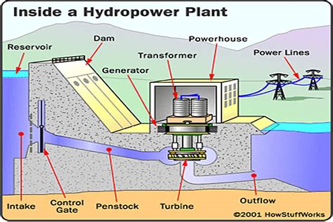
First important component in generating electricity at a hydroelectric station is falling water. We can have falling water by building a dam on a river, like Hoover Dam on Colorado river or use natural difference in the level of water of the waterfalls, like at Niagara falls.

Having the water at two levels, we should direct the flow from top to bottom onto turbines through pipes. Amount of electricity that can be generated obviously depends on the amount of potential energy water at the top has relatively to the bottom level. As the water falls through the pipes onto turbine, its potential energy is converted into kinetic energy of moving water. This is how much energy we can use to generate electricity. It depends on the amount of water flowing through pipes and the height difference between the top and the bottom levels.

Let's assume that the amount of water falling down through pipes from top to bottom level is M (kg/sec) and the difference in height from top to bottom is H (m).
That means that the amount of energy falling water is losing per unit of time is
Pwater = M·g·H (J/sec or W)

Then we have to solve a purely technical problem to convert this energy into rotational energy of turbines.


Different designs of turbines have been used and tested during a long time of using hydroelectric power. Contemporary turbines are pretty efficient in this process of conversion, but still far less than 100% effective. Losses of energy always exist, and we need some coefficient of efficiency of a turbine to get exact amount of rotational energy produced by falling water.
Let's assume that k is such a coefficient. It has a value from 0 (absolutely ineffective conversion) to 1 (full energy amount of falling water is converted into rotational energy of a turbine). Then the amount of rotational energy produced by turbines per unit of time is
Pturbine = k·M·g·H

Next step is to convert rotational energy of turbines into electric energy.
This is done by generators, which we discussed in previous lectures.


The contemporary generators are pretty effective with norm being above 90%, so we can assume that the coefficient of effectiveness k introduced above encompasses both effectiveness of converting energy of falling water into rotation of turbines and conversion of rotation into electric energy.
So, overall energy produced by a hydroelectric power station per unit of time (that is, the power produced) is
P = k·M·g·H
The hydroelectric power stations can be very large and can produce a lot of electric energy. The most powerful electric power stations are hydroelectric. The problem is, there are not too many rivers suitable for building hydroelectric power stations and an environmental effect of building a hydroelectric power station can be significant.

At the same time, the hydroelectric power stations are pretty efficient, the coefficient k in the formula above can be above 0.8, which means that about 80% of the power of water falling on turbines is effectively converted into electric power.


Coal Burning Stations

Almost a third of electricity generated in the world is produced by fossil fuel burning power stations.
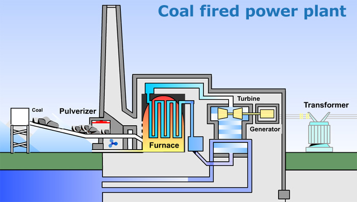
Let's examine the coal burning power station.


The main steps of producing electricity by burning fossil fuel are
(a) burning fossil fuel to boil water, converting chemical energy of burning fuel into kinetic energy of produced steam,
(b) converting kinetic energy of steam into rotation of turbines,
(c) converting rotational energy of turbines into electricity by generators.

Coal is a major source of fossil fuel with natural gas and oil following.
Convenience of putting a coal burning electric power station anywhere should be weighed against environmental impact of such a plant.

Producing energy from burning coal is not a very efficient way to extract chemical energy. Significant portion of the energy produced by burning coal is wasted on each step and the overall efficiency of such a power station is about 40%. Most of the energy losses occur during the first stage of generating electricity - burning coal to boil water and produce steam.
Some efficiency can be achieved by pulverizing coal to powder. However, the main product of burning fossil fuel - carbon dioxide CO2 - produces some unavoidable negative environmental effect.


Nuclear Power Plants

The difference between a nuclear power plant and coal burning one is at the first stage to boil the water. While at coal burning plants the source of heat to boil water is burning coal, at the nuclear power plant the source of heat is energy released by breaking nuclei of heavy elements, like Uranium or Plutonium, into lighter components using neutrons.


The main steps of producing electricity in a nuclear power plant are
(a) bombarding the enriched radioactive material (Uranium, Plutonium or other) with neutrons causing the nuclei of this material to break, releasing certain amount of heat to boil water getting steam,
(b) converting kinetic energy of steam into rotation of turbines,
(c) converting rotational energy of turbines into electricity by generators.

Efficiency of nuclear power plants is quite limited inasmuch as in coal burning power stations and is about 40%. That is, about 40% of the energy generated by heat is converted into electricity.

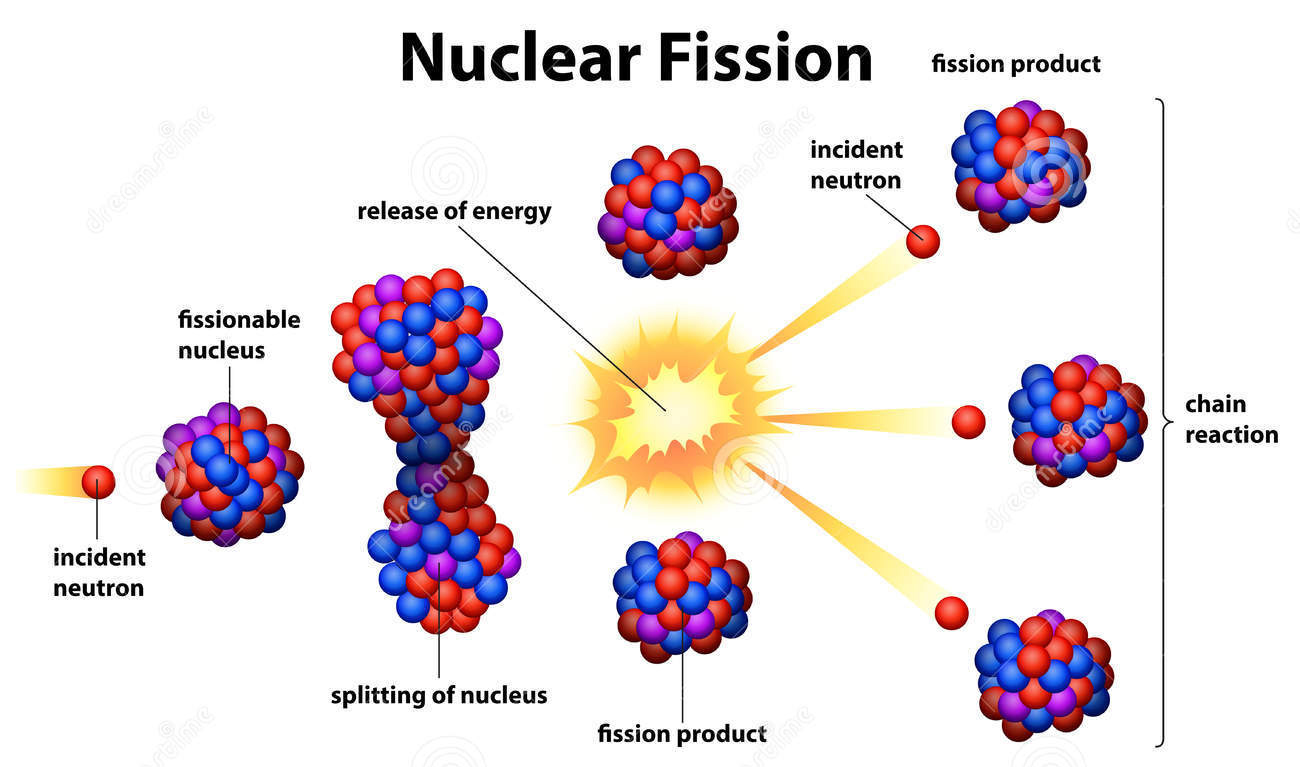
Of interest is a process of nuclear fission that produces the heat. Here is a simplified model of this process.

When a nucleus of Uranium-235 (92 protons + 143 neutrons) is bombarded with a neutron, it temporarily accepts this neutron inside, becoming Uranium-236 (92 protons + 144 neutrons).
This isotope is not stable and a nucleus breaks into different parts. This is a complex process and parts might be different.

A typical scenario might be as follows.
Broken parts are Barium (56 protons + 83 neutrons), Krypton (36 protons + 58 neutrons) and 3 neutrons are released to bombard other nuclei of Uranium 235, causing a chain reaction.

The combined mass of all parts is less than the mass of initial components. The remaining mass of an unstable nucleus of Uranium-236 is converted into radiation (heat, gamma-rays). The heat is used to boil the water, converting it into high energy steam to rotate the turbines.

The corresponding equations describing nuclear fission is:
1n0 + 235U92 → 236U92 →
→
(fission) →
→ 139Ba56 + 94Kr36 + 31n0 + γ


In reality the process is much more complex because the broken parts of a nucleus might be different, themselves not stable and further emitting elementary particles.
The process must be controlled by reducing the number of neutrons flying in all the directions after fission to prevent a nuclear explosion.

Sunday, December 27, 2020

Electricity from Solar Energy: UNIZOR.COM - Physics4Teens - Electromagne...


Notes to a video lecture on http://www.unizor.com

Solar Energy → Electricity

Solar panels that produce electricity are not physically or chemically changed during this process. So, the only source of energy is the light, and the energy it carries is transformed by a solar panel into electricity, that is into movement of electrons.
In this lecture we will analyze how the energy of light forces the electrons to move.
The complete theory behind this process is based on principles of quantum mechanics and we will not be able to dive deep into this area, but a schematic description of the process will be presented.

Commercial solar panel are much more complex that might seem from the following explanation, but their engineering is not a subject of this lecture, which is only about the principle of generation of electricity from sun light.

Let's start with the most important component of a solar cell - silicon (Si).
Silicon is a metalloid, it has crystalline structure and its atoms have four valence electrons on the outer most orbit, next down orbit contains eight electrons and the inner most - two electrons.

Silicon is one of the most frequently occurring elements on Earth and, together with oxygen, forms molecules of silicon dioxide SiO2 - main component of sand.

All silicon atoms are neutral since the number of electrons in each one and the number of protons in each nucleus are the same and equal to 14.
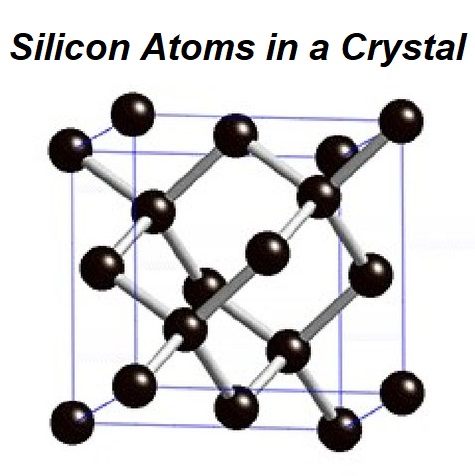
Atoms are connected by their covalent bonds of valence electrons on the outer orbits into a lattice-like crystalline structure.

Picture below represents the crystalline structure of silicon

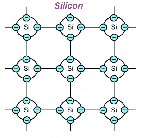
For the purposes of this lecture we will represent inner structure of silicon atoms with only outer orbit of each atom with four valence electrons, as electrons on the inner orbits do not participate in the process of generating electricity from light.

The covalent bonds are quite strong, they do not easily release electrons. As a result, under normal conditions silicon is practically a dielectric.
However, if we excite the electrons sufficiently enough to break the covalent bonds, some electrons will move. For example, if we increase the temperature of a piece of silicon or put it under a bright sun light and measure its electrical resistance, we will observe the resistance diminishing.
That's why silicon and similar elements are called semiconductors.

While excited electrons of any semiconductor decrease its electrical resistance, they don't produce electromotive force because the material as a whole remains electrically neutral.
To build a solar cell that produces electricity under sun light we will introduce two kinds of "impurities" into crystalline lattice of silicon.
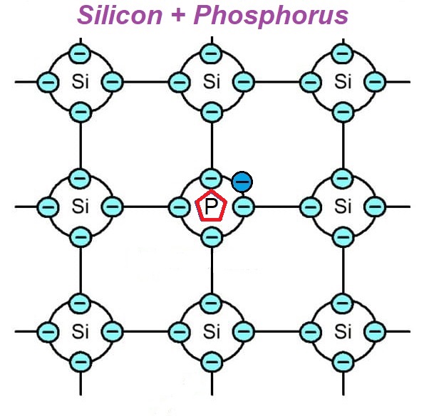
One is an element with five valence electrons on the outer most orbit, like phosphorus (P). When it's embedded into a crystalline lattice of silicon, one electron on that outer orbit of phosphorus would remain not attached to any neighboring atom through a covalent bond.

This creates the possibility for this electron to start traveling, replacing other electrons and pushing them out, which are, in turn, push out others etc. Basically, we create as many freelance electrons as many atoms of phosphorus we add to silicon base.
The whole material is still neutral, but it has certain number of freelance electrons and the same number of stationary positive ions - those nuclei of phosphorus that lost electrons to freelancers.
Silicon with such addition is called n-type (letter n for negative).

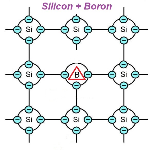
Another type of "impurity" that we will add to silicon is an element with three valence electrons on the outer orbit, like boron (B).
When atoms of boron are embedded into a crystalline lattice of silicon, the overall structure of this combination looks like this

In this case the lattice has a deficiency of an electron that is traditionally called a "hole". Existence of a "hole" opens the opportunity for neighboring valence electrons to fill it, thus creating a "hole" in another spot. These "holes" behave like positively charged particles traveling inside silicon with added boron inasmuch as negatively charged electrons travel in silicon with added phosphorus.
Silicon with such addition of boron is called p-type (letter p for positive).

Now imagine two types of "impure" silicon, n-type and p-type, contacting each other. In practice, it's two flat pieces (like very thin squares) on top of each other.
Let's examine what happens in a thin layer of border between these different types of material.

Initially, both pieces of material are electrically neutral with n-type having free traveling electrons and equal number of stationary positive nuclei of phosphorus inside a crystalline structure and with p-type having traveling "holes" and equal number of stationary negative nuclei of silicon inside a crystalline structure.

As soon as contact between these two types of material is established, certain exchange between electrons of the n-type material and "holes" of the p-type takes place in the border region called p-n junction. Electrons and "holes" in this border region combine, thus reconstituting the lattice.
This process is called recombination.

The consequence of this process of recombination is that n-type material near the border loses electrons, thus becoming positively charged, while the p-type gains the electrons, that is loses "holes", thus becoming negatively charged.

Eventually, the diffusion between n-type and p-type materials stops because negative charge of the p-type sufficiently repels electrons from the n-type. There will be some equilibrium between both parts.

If we introduce heat or bright sun light to electrons of n-type part, the diffusion will be longer and greater charge will be accumulated on both sides of the material - positive on the n-type and negative on the p-type.

Now the key point is to connect n-type side to p-type through some kind of electrical connection and extra electrons from the p_type will go to positively charged n-type, thus creating an electric current. This current is weak because only the diffusion between n-type and p-type in the border region is a contributing factor, but it's still the electric current.

Obviously, the more excited electrons in the n-type material are - the stronger diffusion inside the p-n junction is and the stronger current is produced. That's why, if sun light is used to excite the electrons, the more light falls on the n-type side - the stronger current is produced.

A pair of n-type and p-type materials form a cell. Since we are talking about using sun light to excite electrons, these cells are called solar cells or photovoltaic cells. Cells can be connected in a series increasing the produced electromotive force (voltage) or they can be connected in parallel to increase the electric current (amperage). Solar panels are sets of solar cells connected in series to increase the generated electromotive force (voltage).

Materials used to produce commercial solar cells can be different, not necessarily silicon with phosphorus or boron additions, but the main principle of using p-n junction between superconductors is the same for all.

Sunday, December 20, 2020

Chemical Energy to Electricity: UNIZOR.COM - Physics4Teens - Electromagn...

Notes to a video lecture on http://www.unizor.com

Chemical Energy → Electric Energy

To generate energy, the source components participating in the process should have more energy than the final components of the process. In case of generation of any form of energy from chemical energy we deal with chemical reaction, during which the inter-atomic energy of source components should exceed the inter-atomic energy of products of chemical reaction.

The simple form of such process is burning that produces heat. For example, burning methane CH4 in atmosphere that contains oxygen O2 is a chemical reaction described by
CH4 + 2O2 = CO2 + 2H2O
The inter-atomic energy of one molecule of methane and two molecules of oxygen must be greater than inter-atomic energy of a molecule of carbon dioxide and two molecules of water, otherwise there will not be any energy released as heat.

To generate electric energy from chemical we need the same type of inequality: the inter-atomic energy of primary components of the chemical reaction must be greater than inter-atomic energy of the resulting components.
The way how this excess of energy represented depends on the chemical reaction. In the process of burning the excess of energy is in a form of heat, in case of the generating of electricity the excess of energy is in a form of electric current that has certain voltage and amperage and, therefore, is a carrier of energy.

Transformation of chemical energy into electricity is typically occurring in batteries.
There are different types of batteries, and in this lecture we will mention a few with some details of how they work.

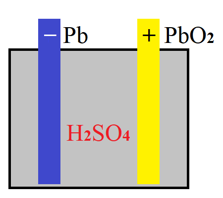
Consider a lead-acid battery used in many cars.
In a simplified way it has three major components: solid anode (negative electrode) made of lead Pb, solid cathode (positive electrode) made of lead dioxide PbO2 and liquid electrolyte in-between them containing sulfuric acid H2SO4 diluted in water H2O.

To understand why electricity is generated by this device, let's look inside the atomic structure of its components and analyze what happens when there is a load (like a lamp) connected to its terminals.

Recall the classical planetary model of an atom.
There are protons and neutrons forming its nucleus and electrons circulating around this nucleus on different orbits.
Those electrons on outer most orbits are less attached to a host nucleus and many of them can fly around, potentially getting attached by other host nuclei.
This creates certain amount of "free" positively (with deficit of electrons) charged ions called cations and negatively (with access of electrons) charged ions called anions.

Analogously, molecules are also not completely stable and can lose atoms, if inter-atomic forces are not strong enough.
Applied to molecular structure of any substance, typical contents not only contains electrically neutral molecules, but also molecules with certain missing or extra atoms or electrons - ions.

Consider sulfuric acid inside a battery pictured above.
Structural composition of atoms of each molecule of this acid can be represented as

Many of electrically neutral molecules of sulfuric acid H2SO4 are partially breaking losing a positive ions (nuclei with a single proton) of hydrogen but retaining their electrons, which can be represented as
H2SO4 → 2H + + SO42−
This can be explained by the fact that hydrogen nucleus contains only one proton, this is the lightest and electrically weakest nucleus and, being so light and volatile, it easily breaks its inter-atomic links with the main molecule of sulfuric acid. The resulting cations H + and anions SO42− are actually responsible for burning and corrosion caused by sulfuric acid. In batteries, however, these ions are responsible for producing electricity.
Here is how.

The negative anode of a lead-acid battery is made of lead (chemical symbol Pb), which, when going into chemical reactions, exhibits either 2 or 4 links to other atoms in the molecules.
The negative ion (anion) SO42−, produced during the breaking of the molecules of sulfuric acid, chemically reacts with led producing lead sulfate, and releasing two electrons left after ions of hydrogen broke free from the molecule of sulfuric acid as follows:
Pb+SO42− → PbSO4 + 2e−
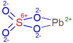
Structural composition of atoms of each molecule of lead sulfate can be represented as


Keep an eye on two electrons 2e− produced at anode. They are produced on the surface of a lead anode and accumulated inside it up to a certain concentration that gives certain negative charge to an anode. These electrons will be the ones that produce the electric current, when some load (like a lamp) is connected to terminals of a battery.

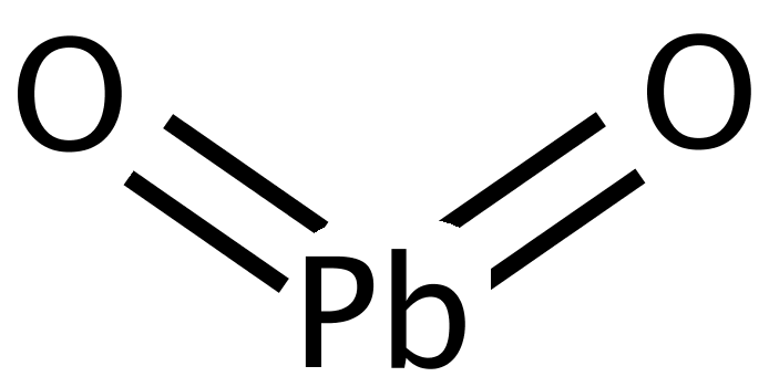
Meanwhile, at the cathode terminal of a led-acid battery another reaction goes on between its main component lead dioxide PbO2, having the following structure

and electrolyte that still contains unused positive ions of hydrogen 2H+ from the reaction on an anode and another pair of ions, positive 2H+ and negative SO42− of the sulfuric acid.

Now two reactions simultaneously go on at the surface of a cathode.
First of all, lead dioxide connects with negative ion of sulfuric acid, producing lead sulfate and releasing two negative ions of oxygen:
PbO2 + SO42− →
→ PbSO4 + 2O−

Secondly, remaining two positive ions of hydrogen from a molecule of sulfuric acid participating in the above reaction and two positive ions of hydrogen from the reaction on an anode meet two negative ions of oxygen from the above reaction, forming two molecules of water H2O with two electrons still missing:
4H+ + 2O− → 2H2O2+

Concentration of these molecules of water missing two electrons creates a positive charge on the cathode terminal of a battery. When this concentration reaches certain level, positive ions of hydrogen cannot reach a cathode, ions of hydrogen are not readily breaking off the molecules of sulfuric acid and reaction stops at certain level of positive charge, unless we connect anode and cathode through some external electric load to allow accumulated on an anode electrons compensate missing electrons on a cathode.

So, we have a shortage of two electrons on a cathode terminal of a battery to form electrically neutral molecules of lead dioxide and water, but these two electrons can travel through an outside load between the terminals of a battery from its anode.
The overall reaction on a cathode looks like
PbO2 + 4H+ + SO42− + 2e− →
→ PbSO4 + 2H2O


As a result of these chemical reactions electrons released by a reaction on an anode travel to a cathode through external load, thus creating an electric current.
In an absence of an external load reactions on terminals of a battery continue until some limit of concentration of negative charge on an anode and positive charge on a cathode is reached, after which the reactions stops as further ionization is prevented by accumulated charges.

This is how chemical energy (inter-molecular links) is converted into electrical energy in a lead-acid battery.

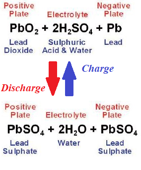
The above described lead-acid battery is capable to work in reverse, to accumulate chemical energy, if external electromotive force is applied to its terminals. In this case all reactions go in reverse, that's how car battery is charged by alternator, when a car is in motion.
The overall picture of the lead-acid battery to discharge and charge is as follows


Monday, December 7, 2020

Electricity from Kinetic Energy: UNIZOR.COM - Physics4Teens - Electromag...

Notes to a video lecture on http://www.unizor.com

Kinetic Energy → Electric Energy

The main principle used in converting kinetic energy into electric is the principle of electromagnetic induction.
Recall the Faraday's Law that defines the induced EMF as being proportional to a rate of changing the magnetic flux
EMF = −dΦ/dt

We can achieve a variable magnetic flux by either rotating the wire frame in the permanent magnetic field or rotating the magnetic field inside the wire frame. The corresponding designs were discussed earlier in this course.

In this lecture we will talk about how we can make a rotation of a rotor in the electric generator.

The simplest form of generating a rotational movement is if we already have some mechanical movement, so all we need is to transform one form of motion (usually, along some trajectory) into a rotational one.

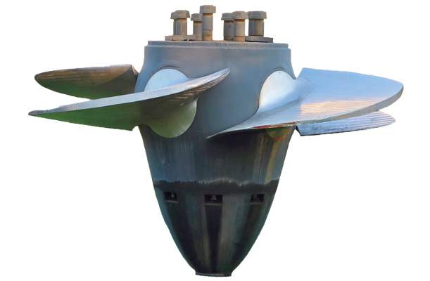
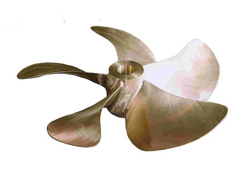
As the first example of such purely mechanical device, consider a propeller.

It can be used to convert the flow of water in hydroelectric plants or the flow of wind through a wind turbine into a rotation. Once we have a rotational motion of the rotor in an electric generator, the rest goes along the previously described way of generation of electricity according to the laws of induction.
It can be a generation of alternating current, including three-phase one, or direct current. These were discussed in details in previous lectures.

In other cases we do not have already available motion that we can transform into a rotation, but we can artificially create one, using some other form of energy.
The common process thermal power station is to generate a flow of steam by heating the water or a flow of some kind of combustion gases. This can be done by using the burners that burn coal, oil or natural gas.
Another way of heating is to use nuclear energy to heat the water by controlling the chain reaction inside the radioactive core of a nuclear reactor.
In some cases the solar energy is used to heat the water to produce a flow of steam.
Rarely used types of heat are geothermal and ocean thermal sources.

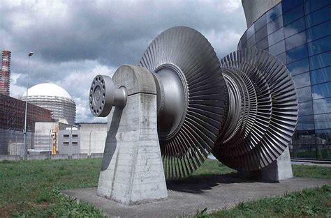
In all these cases some kind of turbines are used to convert the flow of moving substance (water, air, gases, steam) into a rotation.
Steam turbines are just a more sophisticated type of propeller (or rather coaxial propellers), allowing to extract as much as possible energy from the steam flow.


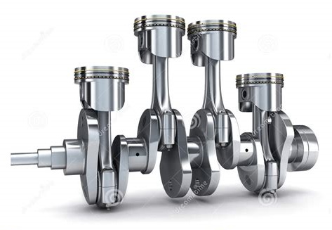
Another form of generating electricity from heat and kinetic energy is internal combustion engines. The work of such engine results in a reciprocating motion of a piston, converted, using a connecting rod and a crankshaft, into rotation of a rotor of an electric generator that generates electricity.


In all the above cases the electricity is produced from kinetic energy of some substance, which is either readily available in nature (like water flowing along a river) or produced as a result of some process (like heating the water to produce a flow of steam).