Electromagnetic Field Equations 3
This lecture is about the third Maxwell equation, expressing in differential form the Faraday's Law of magnetic induction - relationship between magnetic and induced by it electric fields.
This law was introduced in the "Electromagnetism" part of this course, in the topic "The Laws of Induction", which we strongly recommend to refresh.
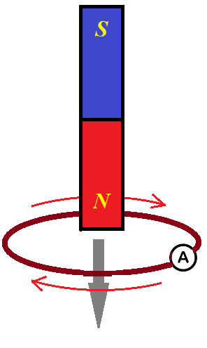
Recall the familiar experiment of a magnet moving through a wire loop that results in an electric current running through a wire loop.

There is no source of electricity that drives the electric current. so we must conclude that moving magnet creates an electric field that moves electrons inside a wire loop.
This electric field exists around a moving magnet whether a wire is there or not, and our task is to quantify this field based on information about changing magnetic field created by a moving magnet.
Consider a changing magnetic field in three-dimensional space. At each point {x,y,z} at each moment in time t it's characterized by a vector B(t,x,y,z) of magnetic field intensity.
Each such magnetic field intensity vector has three components - its projections on three coordinate axes:
Bx(t,x,y,z), By(t,x,y,z) and Bz(t,x,y,z).
If i, j and k are unit vectors along X, Y and Z axes, we can represent any vector of magnetic field intensity as
B(t,x,y,z) = Bx(t,x,y,z)·i +
+ By(t,x,y,z)·j + Bz(t,x,y,z)·k
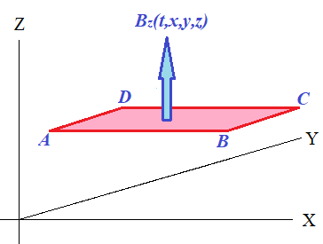
In this lecture we will concentrate on the expression of the intensity of the electric field induced by a variable magnetic field, but initially we will consider only the magnetic field directed along the Z-axis. So, vectors Bx(t,x,y,z) and By(t,x,y,z) equal to zero and only Z-component Bz(t,x,y,z) is not equal to zero and is changing with time.
All magnetic lines of such a magnetic field are parallel to Z-axis.
Let's see what electric field is generated by such unidirectional field Bz(t,x,y,z).
Generally speaking, such a magnetic field will induce an electric field E(t,x,y,z) with some X-, Y- and Z-components Ex(t,x,y,z), Ey(t,x,y,z) and Ez(t,x,y,z), however Ez(t,x,y,z) should be equal to zero since electric field induced by Bz(t,x,y,z) must be perpendicular to it.
At any point in space {x,y,z} at any moment in time t the vector Bz(t,x,y,z) is parallel to a Z-axis. The lines of an electric field generated by this magnetic field lie in the plane perpendicular to the vector Bz(t,x,y,z), that is they are parallel to XY-coordinate plane.
To quantify the electric field intensity vector E(t,x,y,z) at point {x,y,z} at time t, consider a closed infinitesimal rectangular circuit ABCD positioned parallel to XY-plane, centered at point {x,y,z}, with sides Δx parallel to X-axis and Δy parallel to Y-axis and coordinates
A(x−½Δx, y−½Δy, z),
B(x+½Δx, y−½Δy, z),
C(x+½Δx, y+½Δy, z),
D(x−½Δx, y+½Δy, z).

This circuit lies in the plane perpendicular to magnetic field intensity vector Bz(t,x,y,z), so the change in this vector's magnitude will induce electric field with some intensity E(t,x,y,z), resulting in electromotive force in a circuit and electric current in it.
As we know from the above referenced topic "The Laws of Induction" of this course, changing magnetic field flux Φ of the magnetic field intensity Bz(t,x,y,z) through this circuit generates the electromotive force U in it that equals to
U = −dΦ/dt
(also know as Lenz's Law)
Since our circuit ABCD is infinitesimal, the magnetic field flux through it can be approximated as
Φ = Bz(t,x,y,z)·Δx·Δy
where the area of a circuit Δx·Δy does not depend on time, but the magnitude of the magnetic field intensity in the Z-axis direction Bz(t,x,y,z) does.
Therefore, the above equation for electromotive force induced in our circuit by changing Z-component of a vector of magnetic field intensity Bz(t,x,y,z) can be written as
U = −[∂Bz(t,x,y,z)/∂t]·Δx·Δy
Note that electromotive force U depends on time t, location {x,y,z} and dimensions of our rectangular circuit Δx and Δy.
The dimensions are infinitesimal variables, that's why we approximated the magnetic field flux by a product of the magnetic field intensity at its center and an area of a circuit to obtain the electromotive force equation.
On the other hand, electromotive force (or voltage) U between two electric field points is a work needed (or performed by a field) to transfer a unit charge from one point to another.
If electric field intensity E (the force on a unit charge) is constant along a trajectory between these two points, the same work is a product of this intensity by the distance between points L:
U = E·L
In case of variable intensity vector E(x,y,z), the differential of voltage dU on an infinitesimal trajectory of the length dL is a product of a projection of a field intensity vector on this trajectory EL(x,y,z) and an infinitesimal distance dL along this trajectory:
dU(x,y,z) = EL(x,y,z)·dL
Let's calculate the electromotive force in our infinitesimal rectangular circuit as a function of an unknown yet electric field intensity vector E(t,x,y,z).
In this circuit the total electromotive force can be represented as a sum of four components along four sides of a circuit, as the current goes around. Along each line we will use a corresponding component of vector E(t,x,y,z):
Ex(t,x,y,z) for a component along X-axis and
Ey(t,x,y,z) for a component along Y-axis
(there is no Z-component as the electric field is perpendicular to Z-component of the magnetic field Bz(t,x,y,z), which is the only one we are considering now).
Since our circuit is infinitesimal, we can use the electric field intensity in the middle of each side as a constant along an entire side.
So, for side AB we will use Ex(t,x,y−½Δy,z),
for side BC we will use Ey(t,x+½Δx,y,z),
for side CD we will use Ex(t,x,y+½Δy,z),
for side DA we will use Ey(t,x−½Δx,y,z).
Now we can construct an expression for voltage U in terms of electric field intensity
U = UAB+UBC+UCD+UDA =
= Ex(t,x,y−½Δy,z)·Δx +
+ Ey(t,x+½Δx,y,z)·Δy −
− Ex(t,x,y+½Δy,z)·Δx −
− Ey(t,x−½Δx,y,z)·Δy
(plus or minus signs in front of each member depend on the direction of a circuit's current to positive or negative direction of the corresponding axis)
Grouping members with the same multiplier Δx or Δy, we obtain
U = [Ex(t,x,y−½Δy,z) −
− Ex(t,x,y+½Δy,z)]·Δx +
+ [Ey(t,x+½Δx,y,z) −
− Ey(t,x−½Δx,y,z)]·Δy
From the Calculus we know that for infinitesimal α we can use the approximation
f(x+α) − f(x) ≅ (df(x)/dx)·α
or
f(x+½α) − f(x−½α) ≅
≅ (df(x)/dx)·α
and the approximation tends to equality as α→0.
Considering the sides of our wire rectangle Δx and Δy are infinitesimal, we can substitute
Ex(t,x,y−½Δy,z) −
− Ex(t,x,y+½Δy,z)
with
−[∂Ex(t,x,y,z)/∂y]·Δy
Analogously,
Ey(t,x+½Δx,y,z) −
− Ey(t,x−½Δx,y,z)
can be replaced with
[∂Ey(t,x,y,z)/∂x]·Δx
Now the expression for an electromotive force U would look like
U = [∂Ey(t,x,y,z)/∂x]·Δx·Δy −
− [∂Ex(t,x,y,z)/∂y]·Δy·Δx
Recall the above expression of U in terms of magnetic flux:
U = −[dBz(t,x,y,z)/dt]·Δx·Δy
Comparing these two expressions for U we conclude that in a limit case, when the size of our rectangular wire loop tends to zero,
U = [∂Ey(t,x,y,z)/∂x]·Δx·Δy −
− [∂Ex(t,x,y,z)/∂y]·Δy·Δx =
= −[∂Bz(t,x,y,z)/∂t]·Δx·Δy
or
∂Ey(t,x,y,z)/∂x−∂Ex(t,x,y,z)/∂y=
= −∂Bz(t,x,y,z)/∂t
or, shorter, considering that all members are functions of a quartet (t,x,y,z),
∂Ey/∂x − ∂Ex/∂y = −∂Bz/∂t
At this point it's easy to come up with analogous equations for two other important cases:
a case of a unidirectional magnetic field with all magnetic field lines parallel to Y-axis with a direction of the vector of magnetic field intensity always parallel to Y-axis at any point in space, but its magnitude can change with time;
a case of a unidirectional magnetic field with all magnetic field lines parallel to X-axis with a direction of the vector of magnetic field intensity always parallel to X-axis at any point in space, but its magnitude can change with time.
For B(t,x,y,z) = By(t,x,y,z) the corresponding equation will be ∂Ex/∂z − ∂Ez/∂x = −∂By/∂t
For B(t,x,y,z) = Bx(t,x,y,z) the corresponding equation will be ∂Ez/∂y − ∂Ey/∂z = −∂Bx/∂t
There is one more step to combine all the obtained results into one short formula.
Recall the triplet of operators of partial differentiation
∇ = {∂/∂x, ∂/∂y, ∂/∂z}
that we used as a pseudo-vector in the "E-M Equations 1" lecture to express the first Maxwell's equation as a scalar (dot) product of this pseudo-vector and a vector of electric field intensity E={Ex,Ey,Ez}.
Using this operator, the first Maxwell's equation looks like
∇·E = ρ/ε
In this case of the third Maxwell equation we will use the same symbol ∇ as a pseudo-vector, but will use it in a vector (cross) product between it and an electric field intensity vector E={Ex,Ey,Ez}.
For this we need to express the result of such a vector product ∇⨯E in coordinate form.
Let's represent each participating vector (or pseudo-vector) in coordinate form using unit vectors i, j and k along X-, Y- and Z-axis correspondingly:
∇ = (∂/∂x)·i + (∂/∂y)·j + (∂/∂z)·k
E = Ex·i + Ey·j + Ez·k
Vector (cross) product of these vectors in coordinate form looks as follows.
∇⨯E = (∂Ex/∂x)·(i⨯i) +
+ (∂Ex/∂y)·(j⨯i) +
+ (∂Ex/∂z)·(k⨯i) +
+ (∂Ey/∂x)·(i⨯j) +
+ (∂Ey/∂y)·(j⨯j) +
+ (∂Ey/∂z)·(k⨯j) +
+ (∂Ez/∂x)·(i⨯k) +
+ (∂Ez/∂y)·(j⨯k) +
+ (∂Ez/∂z)·(k⨯k)
According to the rules of the vector product,
(i⨯i) = 0
(j⨯i) = −k
(k⨯i) = j
(i⨯j) = k
(j⨯j) = 0
(k⨯j) = −i
(i⨯k) = −j
(j⨯k) = i
(k⨯k) = 0
Using the above equations, the general vector product ∇⨯E can be represented in coordinate form as follows
∇⨯E =
= (∂Ez/∂y − ∂Ey/∂z)·i +
+ (∂Ex/∂z − ∂Ez/∂x)·j +
+ (∂Ey/∂x − ∂Ex/∂y)·k
At the same time any general vector of magnetic field intensity can be represented as a vector sum of its coordinate components
B = Bx·i + By·j + Bz·k
Above we derived three differential equations that relate each component of the magnetic field intensity with components of the induced electric field intensity
∂Ey/∂x − ∂Ex/∂y = −∂Bz/∂t
∂Ex/∂z − ∂Ez/∂x = −∂By/∂t
∂Ez/∂y − ∂Ey/∂z = −∂Bx/∂t
Similar vector equations are
[∂Ey/∂x − ∂Ex/∂y]·i =
= −(∂Bz/∂t)·i
[∂Ex/∂z − ∂Ez/∂x]·j =
= −(∂By/∂t)·j
[∂Ez/∂y − ∂Ey/∂z]·k =
= −(∂Bx/∂t)·k
Combining an expression for ∇⨯E and the above three equations, we see that
∇⨯E =
= −(∂Bx/∂t)·i −
−(∂By/∂t)·j −
− (∂Bz/∂t)·k =
= −∂(Bx·i+By·j+Bz·k)/∂t =
= −∂B/∂t
Our final equation, which is the third Maxwell equation that relates induced electric field to a changing magnetic field - the Faraday's Law - is
∇⨯E = −∂B/∂t
where
∇ = {∂/∂x, ∂/∂y, ∂/∂z} is a triplet of operators of partial differentiation interpreted as a pseudo-vector for convenience,
E = E(t,x,y,z) is the intensity of an induced electrical field and
B = B(t,x,y,z) is the intensity of the magnetic field tha changes with the time.


No comments:
Post a Comment