Electronic Logic
Let's analyze how diodes can be used to implement operations of mathematical (and computer) logic.
These are operations on variables that can have only two possible values - TRUE (in many cases represented by number 1) and FALSE (represented by 0).
TRUE and FALSE in Electronics
First of all, we have to agree on what represents logical TRUE and FALSE or 1 and 0 in electrical circuits.
The standard is that TRUE or 1 is represented by some positive potential on a wire relative to ground, while FALSE or 0 is represented by zero potential relative to ground.
Consider the following circuit
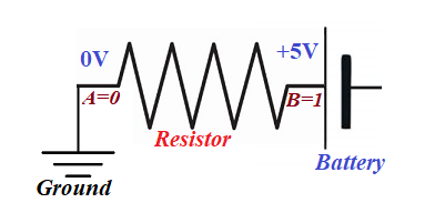
According to our rules about what represents logical TRUE (1) and FALSE (0), the logical value at point A is FALSE (0) and at point B it is TRUE (1).
Binary logical operations
Disjunction OR (sometimes represented by symbol of addition + or vertical bar |).
The rules are: 0|0=0, 0|1=1, 1|0=1, 1|1=1
Conjunction AND (might be represented by symbol of multiplication · or ampersand &),
The rules are: 0&0=0, 0&1=0, 1&0=0, 1&1=1
Exclusive disjunction XOR (might be represented by symbol ⊕).
The rules are: 0⊕0=0, 0⊕1=1, 1⊕0=1, 1⊕1=0
Unary logical operation
Negation NOT (sometimes represented by exclamation sign ! or symbol ¬).
The rules are: ¬0=1, ¬1=0
Implementation
Implementation of binary logical operations in electronics involves developing a schema with two input contacts, A and B, and one output contact C. On two input contacts there might be four different combinations of electric potential:
A=0, B=0
A=0, B=1
A=1, B=0
A=1, B=1
For each of these combinations the value of electric potential at output point C should correspond to the rules of the corresponding binary logical operation implemented in this schema.
Implementation of unary logical operations in electronics involves developing a schema with one input contacts A and one output contact B. On input contact A there might be two different electric potentials:
A=0
A=1
For each of these combinations the value of electric potential at output point B should correspond to the rules of the corresponding unary logical operation implemented in this schema.
Examples of implementation of certain logical operations in electronics are presented in subsequent lectures.

No comments:
Post a Comment