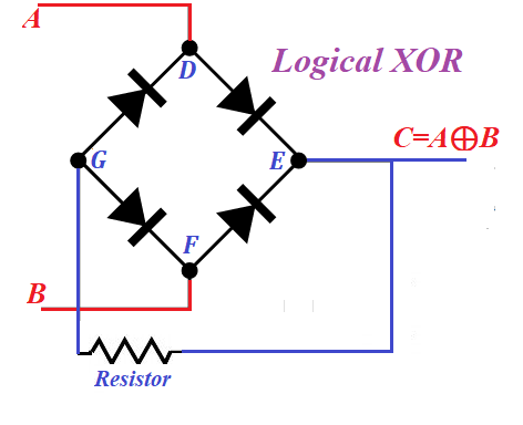
Logical XOR Implementation
Let's analyze how diodes can be used to implement operation XOR (or addition by modulo 2) of mathematical (and computer) logic.
The standard is that TRUE or 1 is represented by some positive potential on a wire relative to the ground, while FALSE or 0 is represented by zero potential relative to the ground.
Exclusive OR (XOR) operation is represented by a symbol of addition in a circle ⊕.
The rules are:
0 ⊕ 0 = 0
0 ⊕ 1 = 1
1 ⊕ 0 = 1
1 ⊕ 1 = 0
Now let's design a schema that represents a logical operation XOR of two logical values.
There are four variations of input values A and B:
A=0, B=0
A=0, B=1
A=1, B=0
A=1, B=1
For each of these cases we will determine the output value at point C.
1. If A=0 and B=0, that is the potential is zero at both points relative to the ground and points D and F are at zero potential as well. In theory, electrons from hot cathodes in diodes at segments ED and EF can move to corresponding anodes only if these anodes are positively charged. But this is not the case since the potentials at points D and F are zero. Therefore, no electrons escape point E. Point G is connected only to anodes and, therefore, no electrons escape this point either. So, at point C the potential is zero, that is C=0
2. Consider a case of A=0 and B=1, that is the potential is zero at points A and D, but is positive (deficiency of electrons) at points B and F relative to the ground.
A diode on a segment EF has its anode positively charged from point F. Therefore, electrons in the cloud produced by thermionic emission on its cathode will be attracted to positively charged anode, thus creating a deficiency of electrons (positive potential) on this cathode and at points E and C. Point C becomes positively charged, that is C=1.
Deficiency of electrons at point E cannot be compensated through a segment DE because a diode on this segment is working in an opposite direction. So, deficiency of electrons will be compensated from point G from point G, which becomes positively charged and attracts electrons from point D through a diode at segment DG. These new electrons, coming from point A to point D, through thermionic emission to point G and to point E, will be immediately dispatched to a thermionic emission cloud and attracted by positively charged anode of a diode on EF segment, thus maintaining a constant flow of electrons from point G (neutral) to point E (positive).
This process of electrons moving from zero potential at point A to point D, to thermionic emission cloud on a cathode of DG segment, to point G, to point E will continue as long as point B has positive potential.
Therefore, the cathode of a diode on a segment EF will always be positively charged, and so is a wire at points E and C connected to it. That means that C=1.
3. If A=1 (positively charged, that is deficiency of electrons) and B=0 (neutral), situation is analogous to a previous one, except all the electrons will flow from point B to point F, to cathode of a diode on a segment FG to point G, to point E, to thermionic cloud of a cathode on segment ED to positively charged points D and A. Since there is a deficiency of electrons at point E, the potential at point C will be positive, that is C=1.
4. Case A=1 and B=1 (both deficient of electrons). There is no source of electrons to compensate this deficiency. If point E was connected to such a source, there would be a flow of electrons from it through segments ED and EF, but this is not the case. No electrons are moving through point G either. Therefore, potential at points E, G and C is zero, that is C=0
As we see, if any one input potentials at points A and B equal to 1, the output C=1 as well. If both A=0 and B=0, the potential at C is zero, that is C=0. If both A=1 and B=1, the potential at C is also zero, that is C=0.
That fully corresponds to the rules of logical XOR operation.
Therefore, the circuit above is a proper electronic implementation of logical operation of exclusive OR (or addition by modulo 2).
Obviously, the real implementation requires some concrete values for voltage, resistance, characteristics of diodes etc. that we will not address here, as our purpose is to introduce only the principle behind this implementation.

No comments:
Post a Comment