Logical AND Implementation
Let's analyze how diodes can be used to implement operation AND of mathematical (and computer) logic.
The standard is that TRUE or 1 is represented by some positive potential on a wire relative to ground, while FALSE or 0 is represented by zero potential relative to ground.
Conjunction AND is represented by a symbol of multiplication · or an ampersand &.
The rules are:
0 & 0 = 0
0 & 1 = 0
1 & 0 = 0
1 & 1 = 1
Now let's design a schema that represents a logical operation AND of two logical values.
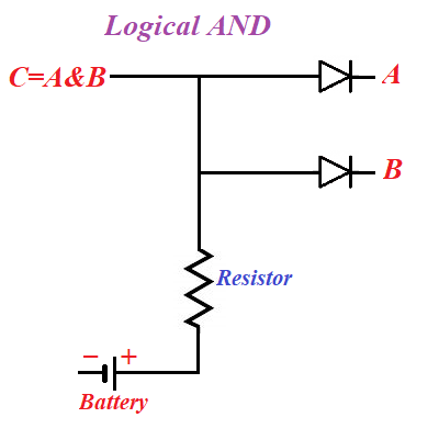
Here points A and B are on the cathode sides of corresponding diodes, while both anodes are connected to a positive potential wire from a battery.
If both A and B represent the value of 1 (that is, have positive potential and deficiency of electrons), there is no difference in potentials between anodes and corresponding cathodes, no thermionic clouds and the potential at point C will be positive, that is C=1 in this case.
If the potential at point A or at point B, or at both of these points is maintained at 0, electrons from thermionic cloud will fly to a corresponding anode and, further, neutralize any positive potential (deficiency of electrons) that might exist at point C.
Therefore, in this case the logical value at point C will be equal to 0.
This is exactly the same as the definition of logical operation AND between two boolean variables A and B.
Therefore, the circuit above is a proper electronic implementation of logical operation of conjunction.
Obviously, the real implementation requires some concrete values for voltage, resistance, characteristics of diodes etc. that we will not address here, as our purpose is to introduce only the principle behind this implementation.

No comments:
Post a Comment